led drive circuit

An LED driver and circuit technology, applied in circuits, electrical components, semiconductor devices, etc., can solve the problems of circuit miniaturization and circuit cost reduction, difficulty in reducing chip size, etc., to prevent through current, eliminate the deviation of light emission, The effect of improving the light-emitting duty cycle

Active Publication Date: 2016-08-10
CITIZEN WATCH CO LTD +1
View PDF7 Cites 0 Cited by
  • Summary
  • Abstract
  • Description
  • Claims
  • Application Information

AI Technical Summary

Problems solved by technology

Furthermore, an analog switch requires at least 3 terminals, and it is difficult to reduce the chip size for an analog switch with high withstand voltage and low resistance
Therefore, there are disadvantages that it is difficult to reduce the size of the circuit and reduce the cost of the circuit.

Method used


Image

  • led drive circuit
  • led drive circuit
  • led drive circuit

Examples


Embodiment Construction

[0037] Hereinafter, the LED drive circuit will be described with reference to the drawings. However, the technical scope of the present invention is not limited to these embodiments, but relates to the invention described in the claims and its equivalents.

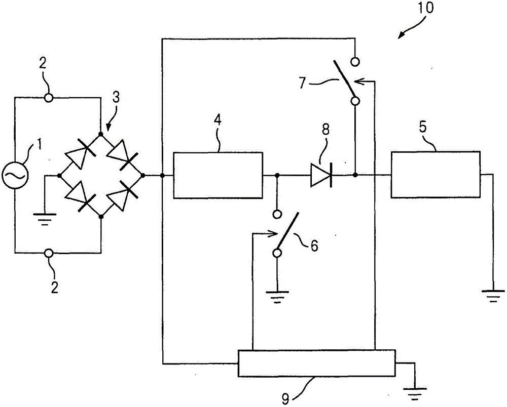
[0038] figure 1 It is a schematic explanatory diagram of the LED drive circuit.

[0039] LED drive circuit 10 such as figure 1 As shown, it includes: a connecting terminal connected to a commercial power supply (AC 100V) 1, a diode bridge circuit 3 for full-wave rectification, a first LED block 4 including a plurality of LEDs, a second LED block 5 including a plurality of LEDs, and a first The switch 6, the second switch 7, the reverse current prevention diode 8 for preventing through current, the control circuit 9, and the like.

[0040] The first LED block 4 and the second LED block 5 are formed by serially connecting 16 white LEDs with Vf=3.2V (power consumption 64mW, beam 5lm). Therefore, in each LED block alone, when the...


PUM


Abstract

An object of the present invention is to provide an inexpensive and compact LED drive circuit capable of efficiently preventing through current between a plurality of LED groups. The LED driving circuit is characterized in that it has: a rectifier; a first LED group including a plurality of LEDs; a second LED group including a plurality of LEDs; 1 and the second LED group; a control unit controlling the connection unit to switch the first and second LED groups from parallel connection to series connection with respect to the rectifier; and a reverse current preventing diode arranged between the first LED group and the second LED group.

Description

Technical field [0001] The present invention relates to an LED drive circuit, and more particularly, to an LED drive circuit for performing efficient LED light emission using AC power. Background technique [0002] There is known a light-emitting LED driving circuit for lighting that applies a rectified voltage output from a bridge diode to a plurality of LEDs connected in series to emit light. The bridge diode performs full-wave rectification on an AC power supplied from a commercial power source. (For example, refer to Patent Document 1). [0003] In the LED, when a voltage equal to or higher than the forward drop voltage (Vf) is applied to the LED, light emission with a luminosity approximately proportional to the forward current (If) is performed. Therefore, when n multiple LEDs are connected in series, when a voltage of n×Vf or more is applied to the multiple LEDs, the multiple LEDs emit light. In addition, for the rectified voltage output from the bridge diode that performs...

Claims


Application Information

Patent Timeline
Patent Type & Authority Patents(China)
IPC IPC(8): H01L33/00
CPCH05B45/44
Inventor 秋山贵
Owner CITIZEN WATCH CO LTD
Why Eureka
Try Eureka