Supercharge Your Innovation With Domain-Expert AI Agents!

Method and apparatus for reconfiguring mapping of carrier indicator fields to component carriers

A technology of carrier indicator and component carrier, applied in the direction of modulated carrier system, digital transmission system, multiple use of transmission path, etc., can solve the problems of performance degradation, call loss, etc., and achieve the effect of avoiding connection performance degradation

Active Publication Date: 2015-09-16
TELEFON AB LM ERICSSON (PUBL)
View PDF2 Cites 0 Cited by
  • Summary
  • Abstract
  • Description
  • Claims
  • Application Information

AI Technical Summary

Problems solved by technology

This can lead to dropped calls and reduced performance

Method used


Image

  • Method and apparatus for reconfiguring mapping of carrier indicator fields to component carriers
  • Method and apparatus for reconfiguring mapping of carrier indicator fields to component carriers
  • Method and apparatus for reconfiguring mapping of carrier indicator fields to component carriers

Examples


Embodiment Construction

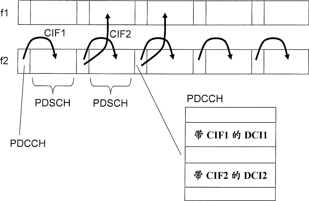
[0038] Throughout the following description, similar reference numerals have been used to denote similar elements, parts, nodes, systems, items or features, where applicable. exist Figure 7 , 8 In and 9, different examples of CIF-enabled component carriers and CIF-disabled component carriers are shown. exist Figure 7 , disable CIF, and in Figure 8 and 9 , enable CIF. in addition, Figure 8 shows a configuration where the mapping of CIF values ​​to component carriers is the same as Figure 9 The configurations shown show a different mapping of CIF values ​​to component carriers.

[0039] Figure 6 A schematic overview of an exemplary multi-carrier radio communication system 100 in which embodiments may be implemented is shown. The multi-carrier radio communication system 100 comprises a radio network node 130 and a user equipment 120 . The arrows indicate that the user equipment 120 may exchange information with the radio network node 130 using eg a downlink contro...


PUM


Abstract

A method and an arrangement in a radio network node for reconfiguring mappings from Carrier Indicator Field-values to component carriers are provided. Each CIF-value is mapped to a respective component carrier comprising a respective shared data channel. Each respective shared data channel corresponds to at least one downlink control channel carrying said each CIF-value. The radio network node reconfigures mappings from CIF-values to component carriers, while at least one mapping of CIF-value to component carrier is maintained. The component carrier of said at least one mapping from CIF-value to component carrier comprises said at least one downlink control channel and a shared data channel corresponding to said at least one downlink control channel. The radio network node sends at least one of the reconfigured mappings from CIF-values to component carriers to the user equipment.

Description

technical field [0001] The present disclosure relates to methods and apparatus in a multi-carrier radio communication system. In particular, the present disclosure relates to methods and arrangements in a radio network node for reconfiguring the mapping from carrier indicator field values ​​to component carriers. Background technique [0002] LTE (Long Term Evolution) uses OFDM (Orthogonal Frequency Division Multiplexing) in the downlink and DFT-spread OFDM (Discrete Fourier Transform-spread Orthogonal Frequency Division Multiplexing) in the uplink. Therefore, the basic LTE downlink physical resources can be viewed as figure 1 In the time-frequency grid shown, each resource element in the figure corresponds to one OFDM subcarrier during one OFDM symbol interval. [0003] In the time domain, LTE downlink transmissions are organized into 10 ms radio frames, each radio frame consists of 10 subframe = 1 ms of equal size subframes, such as figure 2 shown. [0004] Furthermo...

Claims


Application Information

Patent Timeline
Patent Type & Authority Patents(China)
IPC IPC(8): H04L5/00
CPCH04L5/0094H04L5/0096H04L5/0064H04W72/0453H04L27/2601H04W72/23
Inventor D.拉森R.巴尔德迈尔D.格斯滕贝格尔S.帕克瓦尔
Owner TELEFON AB LM ERICSSON (PUBL)
Features
  • R&D
  • Intellectual Property
  • Life Sciences
  • Materials
  • Tech Scout
  • Unparalleled Data Quality
  • Higher Quality Content
  • 60% Fewer Hallucinations
Learn More