High-accuracy frequency measurement system

A high-precision, frequency measurement technology, applied in the field of instrument systems, can solve problems such as the impact of test accuracy, achieve the effect of reducing impact and improving test accuracy

Inactive Publication Date: 2012-08-22
CHENGDU QIANGFENG TECH
View PDF0 Cites 11 Cited by
  • Summary
  • Abstract
  • Description
  • Claims
  • Application Information

AI Technical Summary

Problems solved by technology

For existing frequency measuring instruments based on vibrating wire sensors, the test accuracy

Method used


Image

  • High-accuracy frequency measurement system
  • High-accuracy frequency measurement system
  • High-accuracy frequency measurement system

Examples


Embodiment Construction

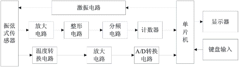
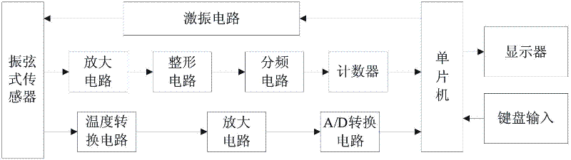
[0010] Such as figure 1 Shown is a high-precision frequency measurement system, including an excitation circuit, a vibrating wire sensor, a sensor vibration measurement circuit and a temperature compensation circuit. The sensor vibration measurement circuit is composed of an amplifier circuit, a shaping circuit, a frequency division circuit and a counter connection , the temperature compensation circuit is composed of a temperature conversion circuit, an amplification circuit and an A / D conversion circuit.

[0011] The system controls the excitation circuit to excite the string through the single-chip microcomputer, so that the vibrating wire sensor outputs a frequency signal, and the I / O port of the single-chip microcomputer sends out a pulse, and uses a high-frequency transformer and a voltage doubler circuit to boost the voltage to generate a high-voltage pulse to excite the vibrating wire. vibration.

[0012] The vibrating wire sensor is a frequency sensor, and its coil i...


PUM


Abstract

The invention discloses a high-accuracy frequency measurement system. The high-accuracy frequency measurement system comprises an excitation circuit, a vibrating wire sensor, a sensor vibration testing circuit and a temperature compensating circuit, wherein the sensor vibration testing circuit consists of an amplifying circuit, a shaping circuit, a frequency dividing circuit and a counter which are connected together; and the temperature compensating circuit consists of a temperature converting circuit, an amplifying circuit and an analog/digital converting circuit which are connected together. The high-accuracy frequency measurement system adopts the temperature compensating circuit, so that the influence of temperature on frequency measurement of the vibrating wire sensor is effectively reduced, and the measurement accuracy is improved.

Description

technical field [0001] The invention relates to an instrument system for measuring frequency, in particular to a high-precision frequency measuring system. Background technique [0002] The vibrating wire sensor has the characteristics of simple structure, high precision, and good long-term stability. The output of the vibrating wire sensor is a frequency signal, and the frequency signal can obtain a high measurement accuracy signal, and is suitable for long-distance transmission without reducing its High precision, easy to interface with microcomputer, and strong anti-interference ability. The vibrating wire sensor works according to the corresponding relationship between its resonant frequency and the pressure it receives. Since the linear expansion coefficients of the vibrating wire and the materials used for its support are different, the frequency will change when the temperature rises and falls, that is, for For the same pressure, if the test environment temperature i...

Claims


Application Information

Patent Timeline
IPC IPC(8): G01R23/10
Inventor 严烽
Owner CHENGDU QIANGFENG TECH
Why Eureka
Try Eureka