Radio frequency test system for mobile communication terminal

A technology of radio frequency test system and mobile communication terminal, which is applied in transmission system, wireless communication, transmission monitoring, etc. It can solve problems such as inability to process a large amount of data, high error rate, and inability to meet the flexibility of R&D and testing, and achieve design redundancy. High, scalable effect

Inactive Publication Date: 2009-05-20
BEIJING WULONG TELECOM TECH
View PDF0 Cites 43 Cited by
  • Summary
  • Abstract
  • Description
  • Claims
  • Application Information

AI Technical Summary

Problems solved by technology

[0005] (1) Manually build the system: the inability to fully calibrate leads to poor test accuracy and the inability to complete complex tests
[0006] (2) Manual setting: low efficiency, poor repeatability, high error rate, unable to complete complex tests
[0007] (3) Manual processing of test results: only simple records, unable to process a large amount of data and high error rate,
[0010] (1) This type of system is only designed for the testing requirements of the certification stage, and the overall software and hardware design can only meet part of the R&D testing requirements, especially the hardware design cannot meet the comprehensive requirements of R&D testing
[0011] (2) The test program is basically fixed, cannot be changed, cannot be custo

Method used


Image

  • Radio frequency test system for mobile communication terminal
  • Radio frequency test system for mobile communication terminal
  • Radio frequency test system for mobile communication terminal

Examples


Embodiment Construction

[0037] The mobile communication terminal radio frequency testing system that the present invention designs is described in detail as follows in conjunction with accompanying drawing:

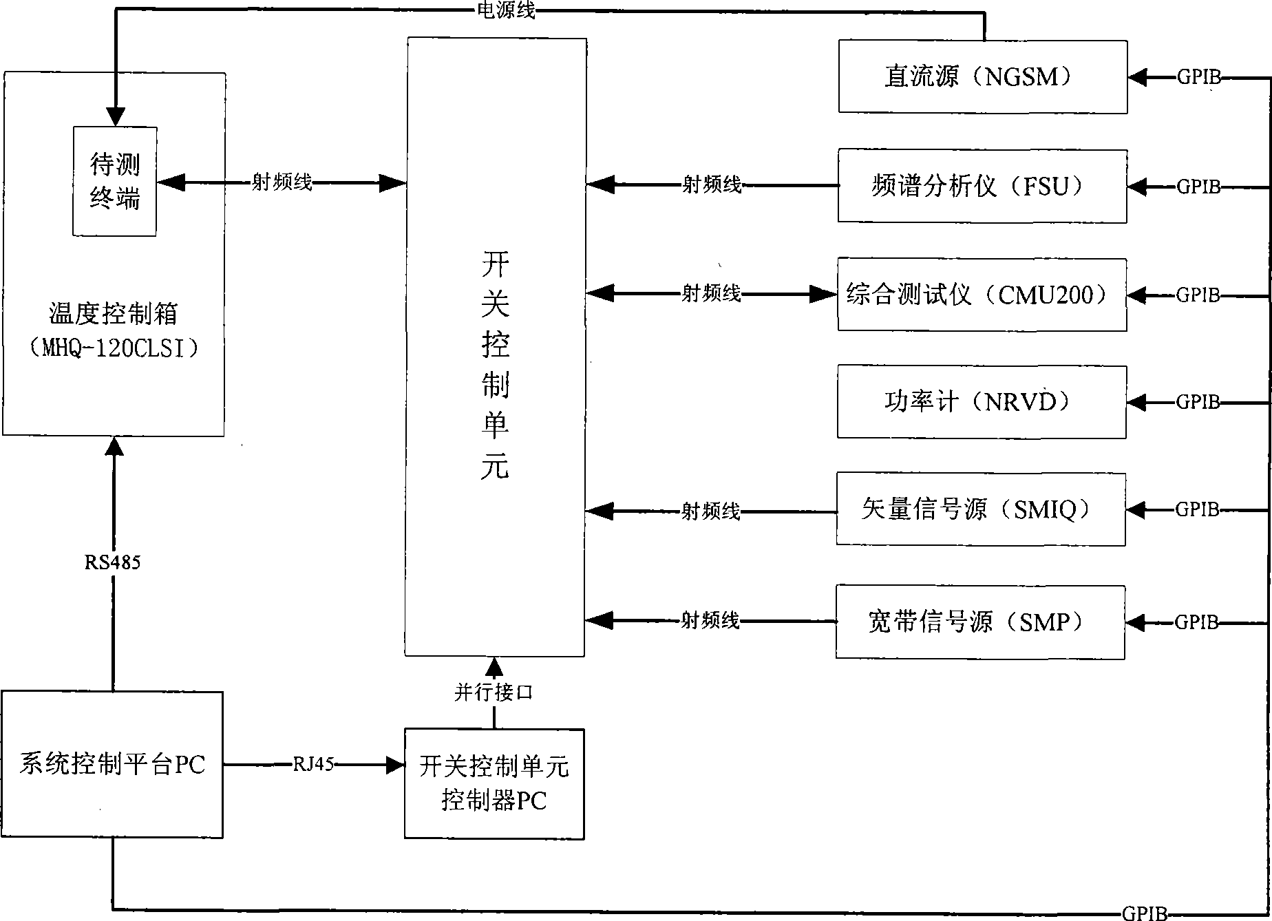
[0038] System overall structure block diagram of the present invention is as figure 1 As shown, the system consists of a comprehensive tester, a spectrum analyzer, a vector signal source, a broadband signal source, a power meter, a DC source, a temperature control box, a switch control unit and its controller, and a system control platform; the system control platform passes The RJ45 interface is connected with the switch control unit controller; the switch control unit controller is connected with the switch control unit through the parallel interface; the system control platform is connected with the temperature control box through the RS485 interface, and the comprehensive tester, Spectrum analyzer, vector signal source, broadband signal source, power meter, and DC source are connected; the c...


PUM


Abstract

The invention relates to a mobile communication terminal radio frequency testing system, which belongs to the field of mobile communication terminal radio frequency test. The system comprises a comprehensive tester, a frequency spectrum analyzer, a vector signal source, a wideband signal source, a power meter, a direct current source, a temperature control box, a switch control unit and a controller thereof , and a system control platform, wherein the system control platform is connected with the controller of the switch control unit, the temperature control box, the comprehensive tester, the frequency spectrum analyzer, the vector signal source, the wideband signal source, the power meter and the direct current source respectively; and the comprehensive tester, the frequency spectrum analyzer, the vector signal source and the wideband signal source are connected with the switch control unit and a terminal to be tested respectively. The system has the advantages of simple operating flow, clear testing process, quick testing, serious processing on testing result, and good reliability and stability; in addition, the system can quickly and accurately develop a test case meeting self requirement, realize diverse and standard test, also can flexibly extend to the control on other instruments and meters, and realize flexible configuration of the system.

Description

technical field [0001] The invention belongs to the field of radio frequency testing of mobile communication terminals, and relates to radio frequency technology, communication technology, electronic measurement technology and system integration technology, in particular to the architecture design of a mobile communication terminal radio frequency testing system. technical background [0002] The radio frequency test of the mobile communication terminal is to ensure that the radio frequency performance of the terminal meets the requirements of relevant international standards. The testing process can be divided into two phases: the research and development phase and the certification phase. The certification phase test is a minimum requirement test, which is completed by a national institution or an international organization to gain market access; at present, the certification phase test, the global national structure or international organization mainly adopts a certified ...

Claims


Application Information

Patent Timeline
IPC IPC(8): H04W24/06H04B17/00
Inventor 李隽宋崇汶孙向前王南陆冰松刘博翰曲岩高勇
Owner BEIJING WULONG TELECOM TECH
Why Eureka
Try Eureka