

Organic light-emitting diode driving circuit, display panel and displayer
A technology of light-emitting diodes and driving circuits, applied in static indicators, instruments, etc., can solve the problems of unstable working state of organic light-emitting diodes, poor Vth uniformity of driving tubes, different driving currents, etc. Good performance and good stability
- Summary
- Abstract
- Description
- Claims
- Application Information
AI Technical Summary
Problems solved by technology
Method used
Image

Examples
Embodiment 1
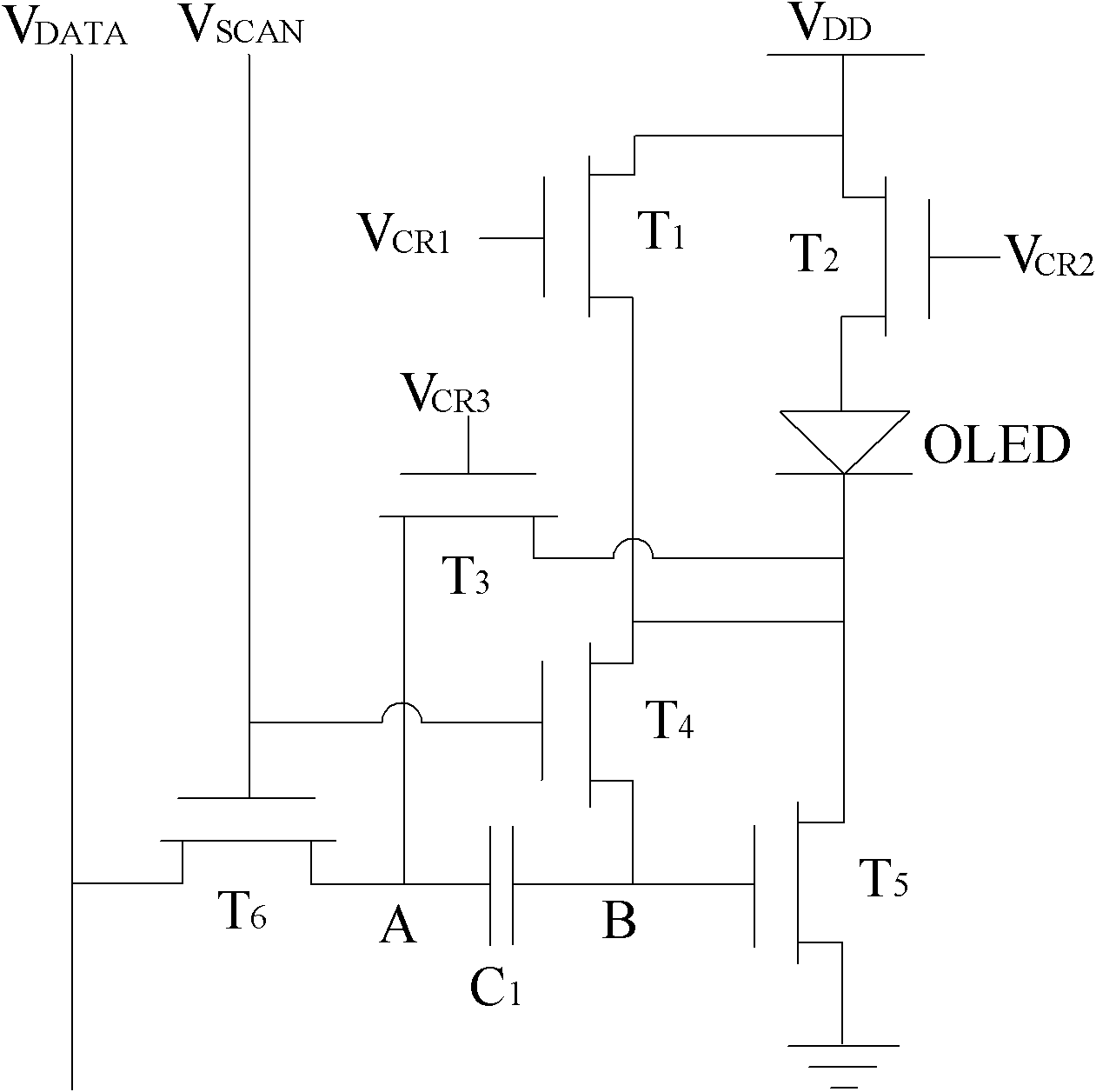
[0028] Embodiment one: if figure 1 As shown, the first preferred threshold compensation unit of the organic light emitting diode drive circuit of the present invention includes:
[0029] The first switching transistor T 1 : The gate is connected to the first control voltage V CR1 , the drain is connected to a high level V DD , the source is connected to the cathode of the organic light emitting diode;
[0030] The second switching transistor T 2 : The gate is connected to the second control voltage V CR2 , the drain is connected to a high level V DD , the source is connected to the anode of the organic light emitting diode;
[0031] The third switching transistor T 3 : The gate is connected to the third control voltage V CR3 , the drain and the source are respectively connected to the cathode of the organic light emitting diode and the A terminal of the capacitor;
[0032] The fourth switching transistor T 4 : Gate connected to scan line V SCAN , the drain and the s...
Embodiment 2
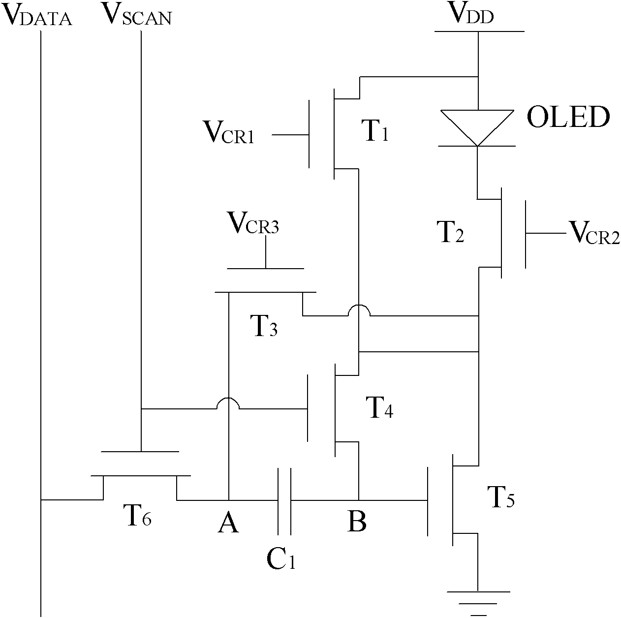
[0046] Embodiment two: if image 3 As shown, the second preferred threshold compensation unit of the organic light emitting diode driving circuit of the present invention includes:
[0047] The first switching transistor T 1 : The gate is connected to the first control voltage V CR1 , the drain is connected to a high level V DD , the source is connected to the cathode of the organic light emitting diode;
[0048] The second switching transistor T 2 : The gate is connected to the second control voltage V CR2 , the drain is connected to the cathode of the organic light emitting diode, and the source is connected to the driving circuit;
[0049] The third switching transistor T 3 : The gate is connected to the third control voltage V CR3 , the drain and the source are respectively connected to the organic light emitting diode cathode and the sixth switching transistor;
[0050] The fourth switching transistor T 4 : The gate is connected to the scan line, the drain and th...
PUM
 Abstract
Description
Claims
Application Information