
Organic light emitting diode driving circuit, display panel, display and driving method

A technology of light-emitting diodes and driving circuits, applied in static indicators, instruments, etc., can solve the problems of unstable working state of organic light-emitting diodes, poor Vth uniformity of driving tubes, different driving currents, etc., and achieve the elimination of inconsistent working states. The effect of good performance and high integration

Inactive Publication Date: 2012-08-29
BOE TECH GRP CO LTD +1
View PDF2 Cites 25 Cited by
  • Summary
  • Abstract
  • Description
  • Claims
  • Application Information

AI Technical Summary

Problems solved by technology

Due to the limitations of the manufacturing process, especially the low-temperature polysilicon technology, the threshold voltage Vth uniformity of the drive tube is very poor and has drift, resulting in different drive currents when the same gray-scale voltage is input.
The inconsistency of the driving current makes the working state of the OLED unstable, which is the main reason why the brightness uniformity of the traditional 2T1C circuit has been poor

Method used


Image

  • Organic light emitting diode driving circuit, display panel, display and driving method
  • Organic light emitting diode driving circuit, display panel, display and driving method
  • Organic light emitting diode driving circuit, display panel, display and driving method

Examples


Embodiment Construction

[0026] The present invention will be described in detail below in conjunction with the accompanying drawings and embodiments.

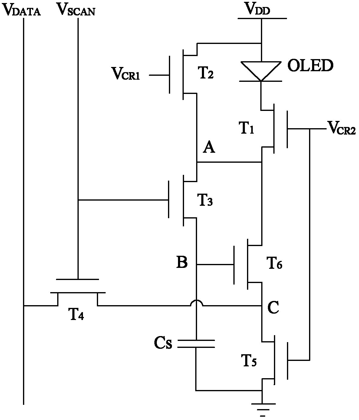
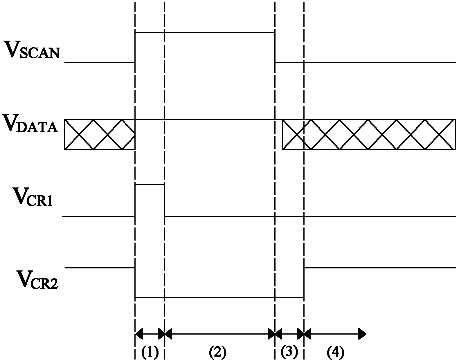
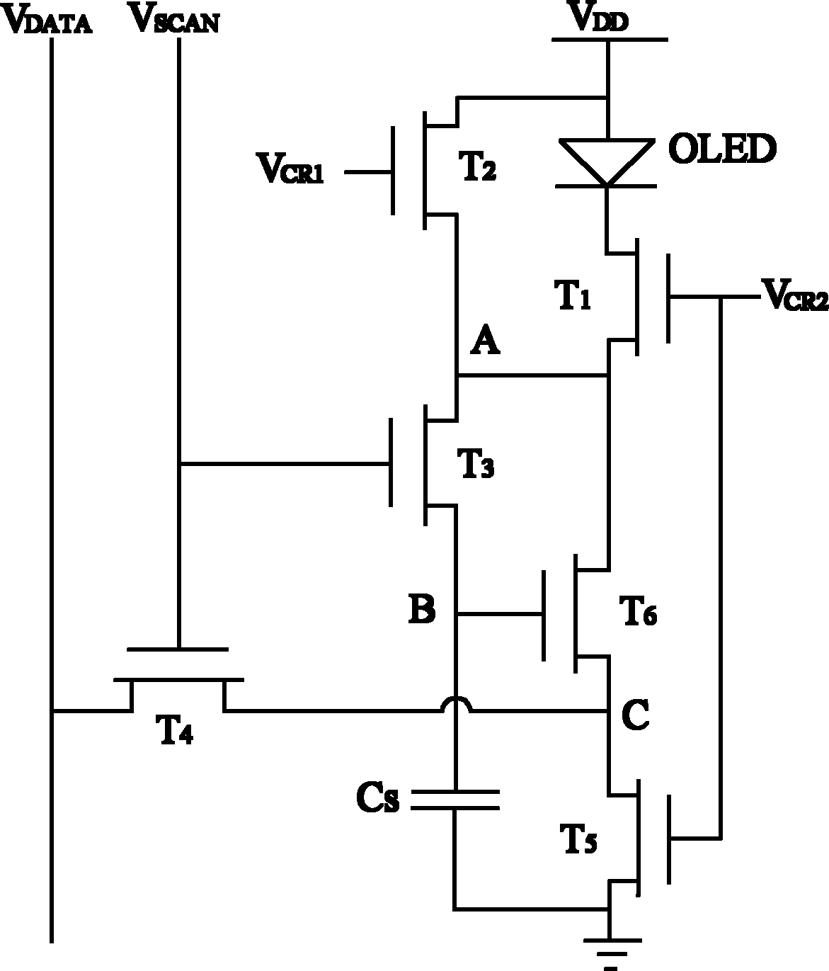
[0027] The organic light emitting diode driving circuit of the present invention uses the diode connection method (Diode Connection) and discharges to form the threshold voltage Vth, that is, uses the threshold compensation principle to compensate the threshold value of the organic light emitting diode driving unit, so as to eliminate the problem caused by the threshold voltage of the driving unit in the overall circuit. The inconsistency of the working state of the organic light-emitting diodes caused by the difference solves the problem of brightness attenuation and unevenness of the organic light-emitting diodes. The driving circuit used includes a driving unit, a threshold compensation unit and an organic light-emitting diode; a plurality of connection terminals of the threshold compensation unit are respectively connected to the data line, the sca...


PUM


Abstract

The invention discloses an organic light emitting diode driving circuit, a display panel which uses the circuit, a display and a driving method, which are designed to solve the problem that the brightness and uniformity of an organic light emitting diode are affected by the threshold voltage of a driving unit of the existing driving circuit. The organic light emitting diode driving circuit disclosed by the invention comprises a driving unit, a threshold compensation unit and an organic light emitting diode. A preferable circuit structure comprises five switching tubes, one driving tube, one capacitor and one organic light emitting diode, wherein the switching tubes and the driving tube are N type thin film transistors preferably. The working principle of the organic light emitting diode driving circuit is that the threshold voltage Vth of the 6T1C circuit compensation driving tube is utilized to eliminate the phenomenon of an inconsistent working state of the organic light emitting diode caused by different threshold voltages of the driving tube of the integrated circuit, thereby solving the problems of brightness and uniformity of the organic light emitting diode.

Description

technical field [0001] The invention relates to an organic light emitting diode display, in particular to a voltage type active matrix organic light emitting diode driving circuit and a driving method. Background technique [0002] The quality of the working state of the organic light-emitting diode directly affects its uniformity and brightness. Organic light-emitting diodes are current-controlling components, and are currently driven by the current generated by thin-film transistors in a saturated state. Due to the limitations of the manufacturing process, especially the low-temperature polysilicon technology, the threshold voltage Vth uniformity of the driving tube is very poor and has drift, resulting in different driving currents when the same gray-scale voltage is input. The inconsistency of the driving current makes the working state of the OLED unstable, which is the main reason why the brightness uniformity of the traditional 2T1C circuit has always been poor. Co...

Claims


Application Information

Patent Timeline
Patent Type & Authority Applications(China)
IPC IPC(8): G09G3/32
CPCG09G3/3233G09G2300/0861
Inventor 谭文祁小敬
Owner BOE TECH GRP CO LTD
Learn More