
Electric connector

A technology for electrical connectors and butt connectors, which is applied to contact parts, electrical components, high-frequency structural connections, etc., can solve problems such as poor terminal alignment, and achieve the effects of improved alignment and impedance balance.

Inactive Publication Date: 2014-03-12
FOXCONN (KUNSHAN) COMPUTER CONNECTOR CO LTD +1
View PDF4 Cites 0 Cited by
  • Summary
  • Abstract
  • Description
  • Claims
  • Application Information

AI Technical Summary

Problems solved by technology

However, there are certain defects in this design. When the terminal is inserted into the mounting hole, the positive position of the terminal will be bad.

Method used


Image

  • Electric connector
  • Electric connector
  • Electric connector

Examples


Embodiment Construction

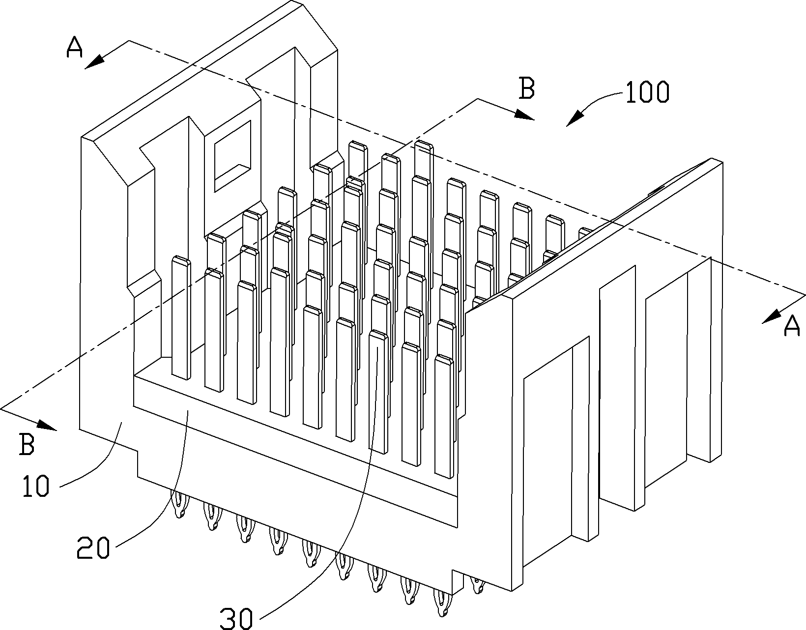
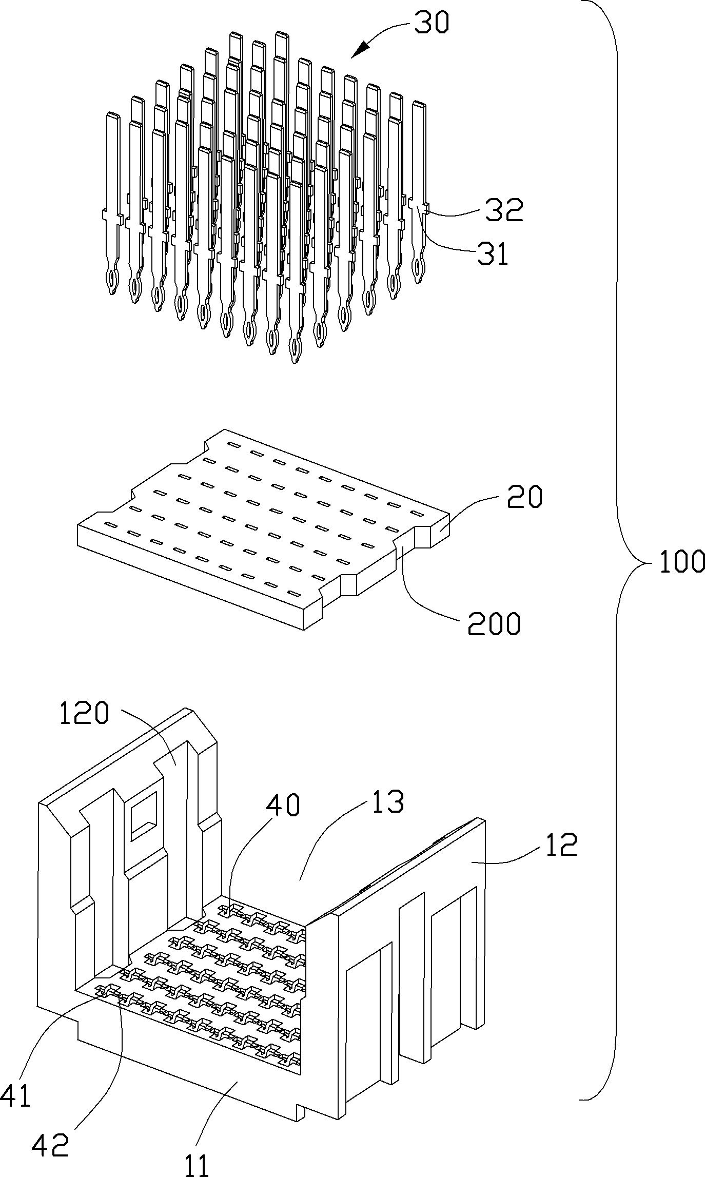
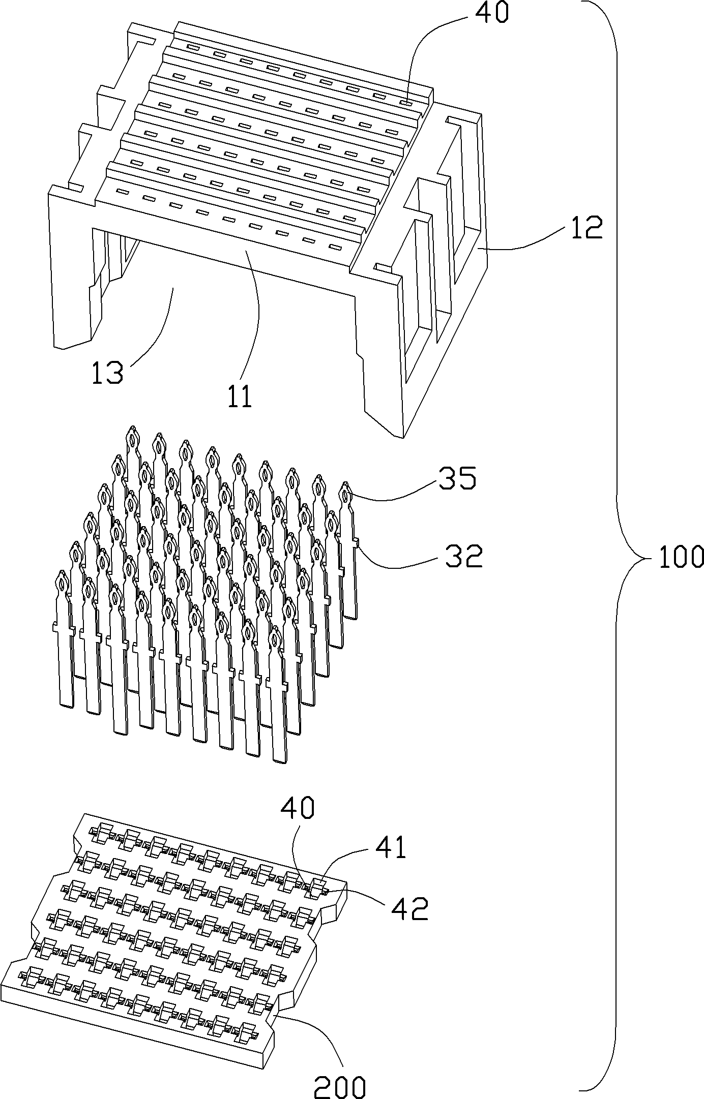
[0013] Such as Figure 1 to Figure 3 As shown, an electrical connector 100 includes a first insulating body 10, a second insulating body 20 mounted on the first insulating body 10, and a plurality of insulating bodies held between the first insulating body 10 and the second insulating body 20. Conductive terminal 30.

[0014] The first insulating body 10 includes a bottom wall 11 and a pair of parallel side walls 12 extending upward perpendicular to the bottom wall 11 at intervals. The bottom wall 11 and the pair of side walls 12 form a storage space for accommodating a mating connector. 13 , the second insulating body 20 is accommodated in the accommodation space 13 . The two sidewalls 12 of the first insulating body 10 are respectively provided with grooves 120 , and the mating connector is provided with a protrusion (not shown in the figure), and the protrusion is received in the groove 120 . The second insulating body 20 is an insulating plate, and two notches 200 are re...


PUM


Abstract

An electrical connector (100) includes a housing having a securing structure and a number of contacts (30). The securing structure defines a number of passageways (40) each extending therethrough along a thickness direction thereof, a number of securing recesses (42) each across and in communication with a corresponding passageway along a width direction thereof, and a number of air pockets (41) each across and in alignment with a corresponding passageway along a length direction thereof. Each contact has a body portion (32) inserted through the passageway, and a widen portion (31) secured in the securing recess and facing a corresponding air pocket.

Description

【Technical field】 [0001] The invention relates to an electric connector, in particular to the structure of the insulating body of the electric connector. 【Background technique】 [0002] At present, in the field of communication, with the continuous increase of signal transmission rate, the design requirements for electrical connectors are also continuously improved. For the prior art related to the present invention, please refer to US Patent No. US 7,074,086 published on September 3, 2003, which discloses an electrical connector, which includes an insulating body and a number of grounding terminals held in the insulating body and a plurality of signal terminals, the insulating body includes a bottom surface and a pair of side walls extending upwards perpendicular to the bottom surface, the bottom surface is provided with a number of mounting holes, and the terminals extend out of the bottom surface through the mounting holes. However, there are certain defects in this desi...

Claims


Application Information

Patent Timeline
IPC IPC(8): H01R13/02H01R13/42H01R13/46
CPCH01R12/585H01R13/719
Inventor 潘锋
Owner FOXCONN (KUNSHAN) COMPUTER CONNECTOR CO LTD
Learn More