Connector, harness and connector assembly

a technology of connectors and connector parts, applied in the direction of coupling contact members, fixed connections, coupling device connections, etc., can solve the problems of degrading the transmission characteristics of the cable connector as a whole, and achieve the effect of preventing the degradation of the transmission characteristics of the connector, reducing the size, and reducing the siz

Active Publication Date: 2021-10-21
JAPAN AVIATION ELECTRONICS IND LTD
View PDF0 Cites 3 Cited by
  • Summary
  • Abstract
  • Description
  • Claims
  • Application Information

AI Technical Summary

Benefits of technology

[0012]The connector according to an aspect of the present invention is a cable connector configured to be connected to a plurality of cables. According to an aspect of the present invention, the first contact portion and the connection portion of each of the signal terminals are apart from each other in the front-rear direction. This structure enables the connector to be reduced in size in the upper-lower direction. Moreover, according to an aspect of the present invention, the ground terminal is removed from the end of the terminal row arranged in the pitch direction. This structure enables the cable connector to be reduced in size in the pitch direction.
[0013]According to an aspect of the present invention, the ground portion, which is a part of the ground member, is arranged outward of the outer signal terminal in the pitch direction. The ground member is connected

Problems solved by technology

As a result, transmission characteristics of th

Method used


Image

  • Connector, harness and connector assembly
  • Connector, harness and connector assembly
  • Connector, harness and connector assembly

Examples


Embodiment Construction

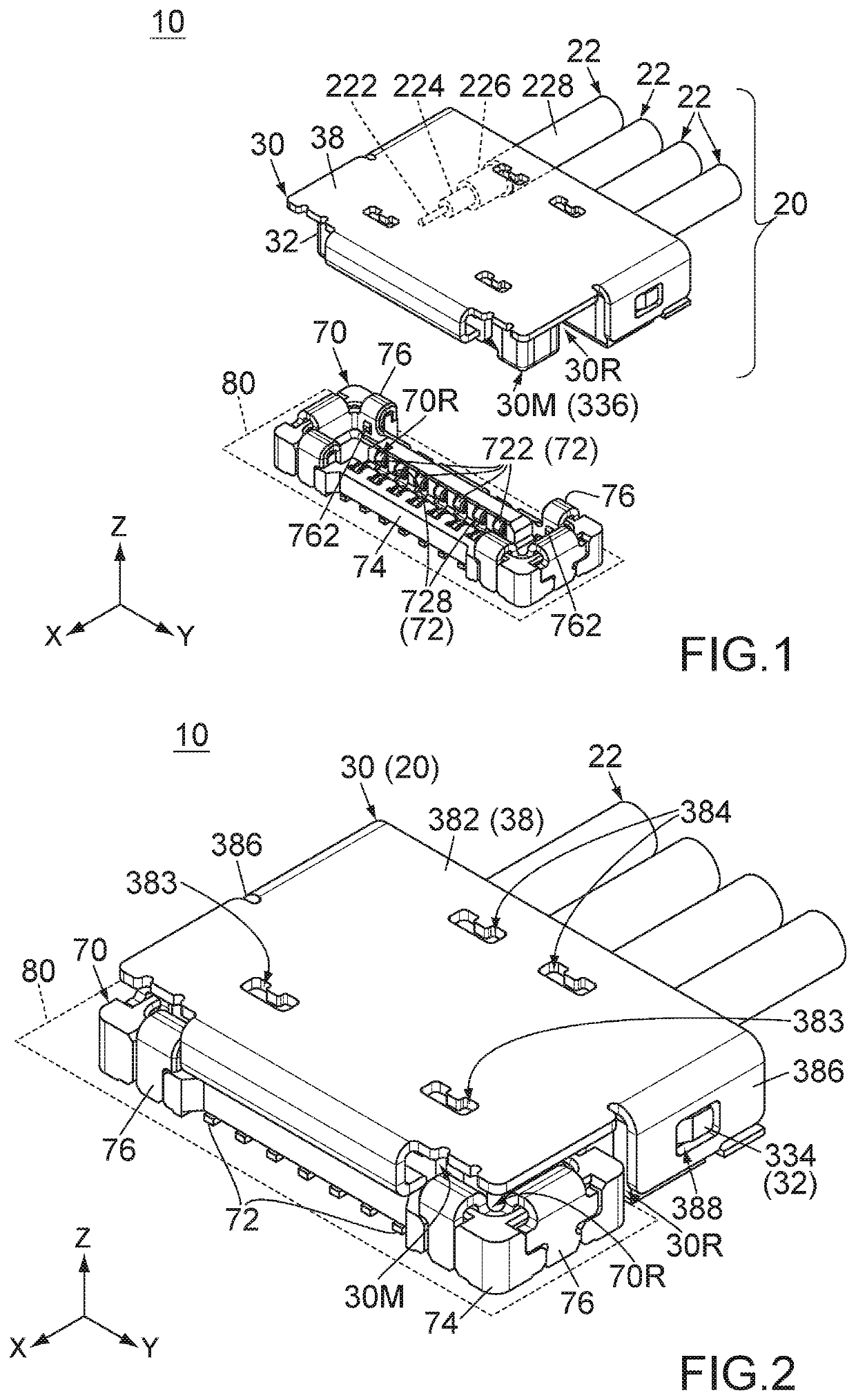
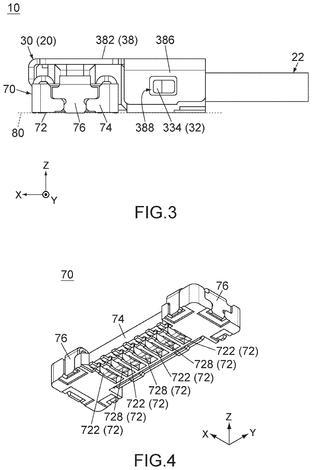
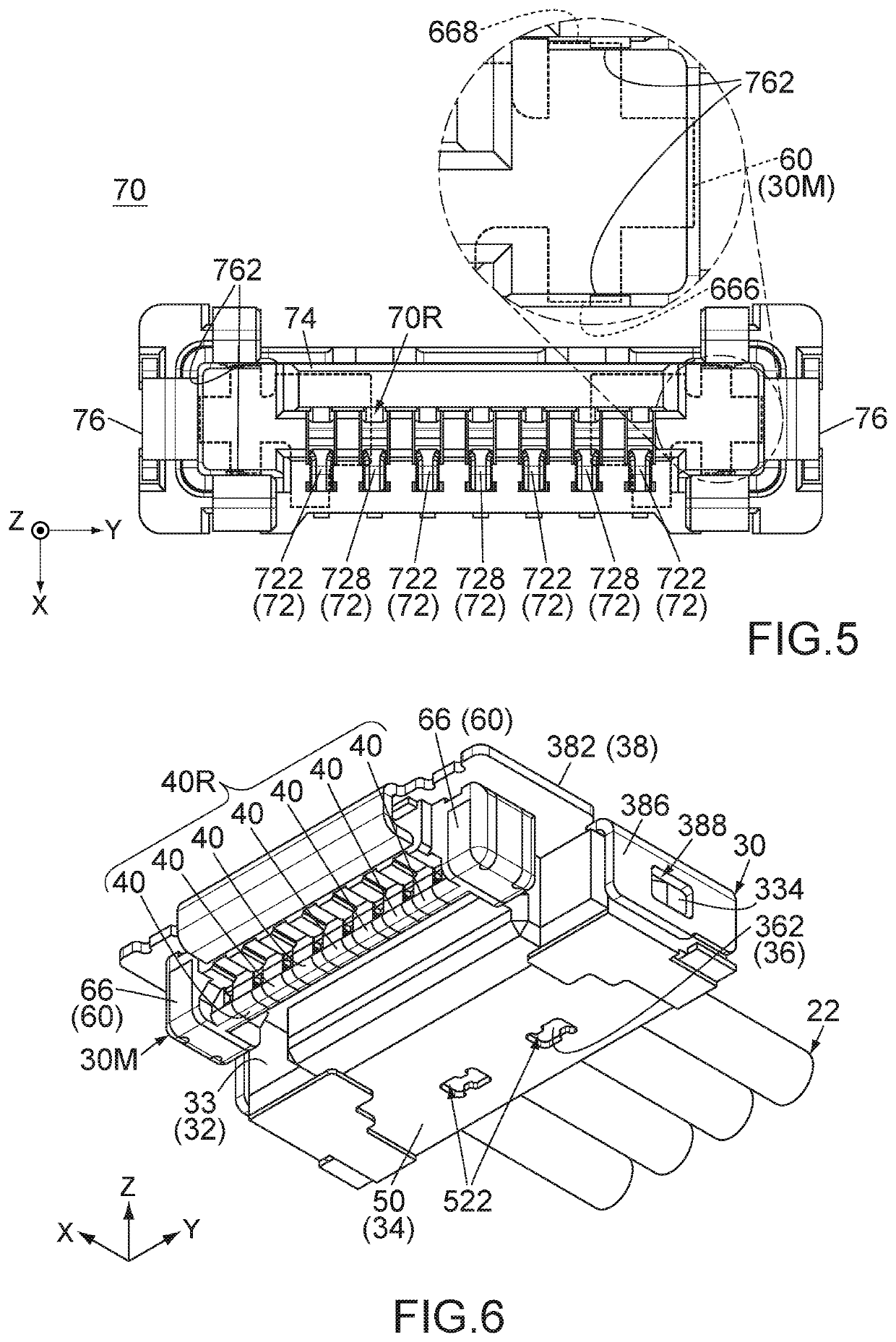
[0039]As shown in FIGS. 1 and 2, a connector assembly 10 according to an embodiment of the present invention comprises a connector 30 and a mating connector 70. The connector 30 is a cable connector configured to be connected to a plurality of cables 22. The connector 30 forms a harness 20 together with the cables 22. Thus, the harness 20 comprises the connector 30 and a plurality of the cables 22. The mating connector 70 is an on-board connector configured to be mounted on a board 80.

[0040]Each of the cables 22 of the present embodiment is a coaxial cable. Each of the cables 22 is connected to an antenna (not shown) and transmits signals of the antenna. The board 80 of the present embodiment is installed in an electronic device (not shown) which sends and receives signals via the antennas. The connector assembly 10 of the present embodiment transmits the signals between the antennas and the electronic device. However, the usage of the cables 22 and the connector assembly 10 of the ...


PUM


Abstract

A connector comprises a plurality of signal terminals, a plurality of ground terminals which are configured to be connected to outer conductors of cables, and a ground member which is configured to be connected to the outer conductors. The ground member has a ground portion. The signal terminals and the ground terminals are alternately arranged in a pitch direction (Y-direction) to form one terminal row. Each of the signal terminals has a first adjustment portion. Each of the ground terminals has a second adjustment portion. The signal terminals include an outer signal terminal located at an end of the terminal row. The first adjustment portion of the outer signal terminal protrudes toward the ground portion. A position of the first adjustment portion of the outer signal terminal in a perpendicular plane (XZ-plane) is equal to or overlaps with a position of the ground portion in the perpendicular plane.

Description

CROSS REFERENCE TO RELATED APPLICATIONS[0001]This application is based on and claims priority under 35 U.S.C. §119 to Japanese Patent Application No. JP 2020-073778 filed Apr. 17, 2020, the content of which is incorporated herein in its entirety by reference.BACKGROUND OF THE INVENTION[0002]This invention relates to a cable connector mateable with an on-board connector.[0003]For example, this type of cable connector is disclosed in JP 2009-32517A (Patent Document 1), the content of which is incorporated herein by reference.[0004]Referring to FIGS. 22 and 23, Patent Document 1 discloses a connector 90 mateable with an on-board connector 95. The connector 90 is connected to a plurality of cables 98 to form a harness. Each of the cables 98 has a core wire 982 and an outer conductor 984. The connector 90 comprises a plurality of contacts (terminals) 92 which correspond to the core wires 982, respectively, and a shell 94 which is connected to the outer conductors 984 to have ground poten...

Claims


Application Information

Patent Timeline
IPC IPC(8): H01R13/6471H01R12/71H01R24/60H01R13/11
CPCH01R13/6471H01R13/11H01R24/60H01R12/716H01R13/6474H01R13/652H01R12/75H01R9/0515H01R12/57H01R13/405
Inventor KIMURA, SHINYA
Owner JAPAN AVIATION ELECTRONICS IND LTD
Why Eureka
Try Eureka