Check patentability & draft patents in minutes with Patsnap Eureka AI!

Video decoding method, encoding method and terminal

A video decoding and video encoding technology, applied in the field of communication, can solve the problems of reduced encoding and decoding performance, frequent memory reading, and large number of candidate motion vectors, and achieves the effect of improving encoding and decoding performance, simplifying hardware design, and reducing frequency.

Active Publication Date: 2015-11-25
HUAWEI TECH CO LTD
View PDF3 Cites 0 Cited by
  • Summary
  • Abstract
  • Description
  • Claims
  • Application Information

AI Technical Summary

Problems solved by technology

[0005] The embodiment of the present application provides a video decoding method, an encoding method, and a terminal to solve the problem that the existing large number of candidate motion vectors leads to frequent reading of memory and reduces the performance of encoding and decoding

Method used


Image

  • Video decoding method, encoding method and terminal
  • Video decoding method, encoding method and terminal
  • Video decoding method, encoding method and terminal

Examples


no. 1 example

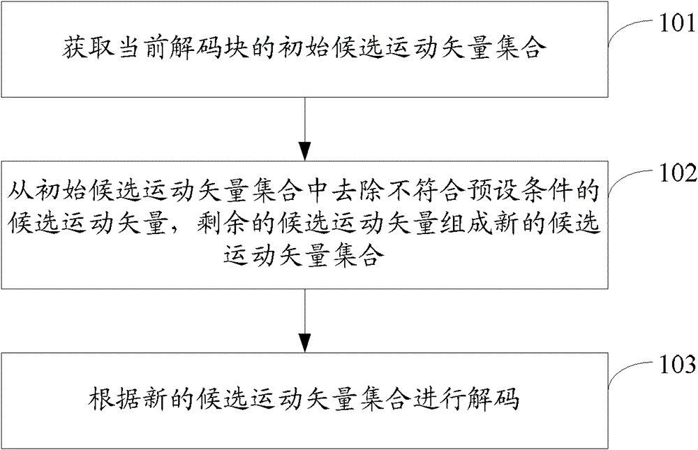
[0043] see Figure 1A , which is the flow chart of the first embodiment of the video decoding method of the present application:

[0044] Step 101: Obtain an initial candidate motion vector set of the current decoding block.

[0045] Specifically, the spatial candidate motion vector can be obtained according to the surrounding decoding blocks of the current decoding block, and the time domain candidate motion vector of the current decoding block can be obtained according to the reference frame. The reference frame is the previous frame of the current frame where the current decoding block is located, or frame, or the previous frame and the next frame, the spatial candidate motion vectors and the temporal candidate motion vectors are formed into an initial set of candidate motion vectors.

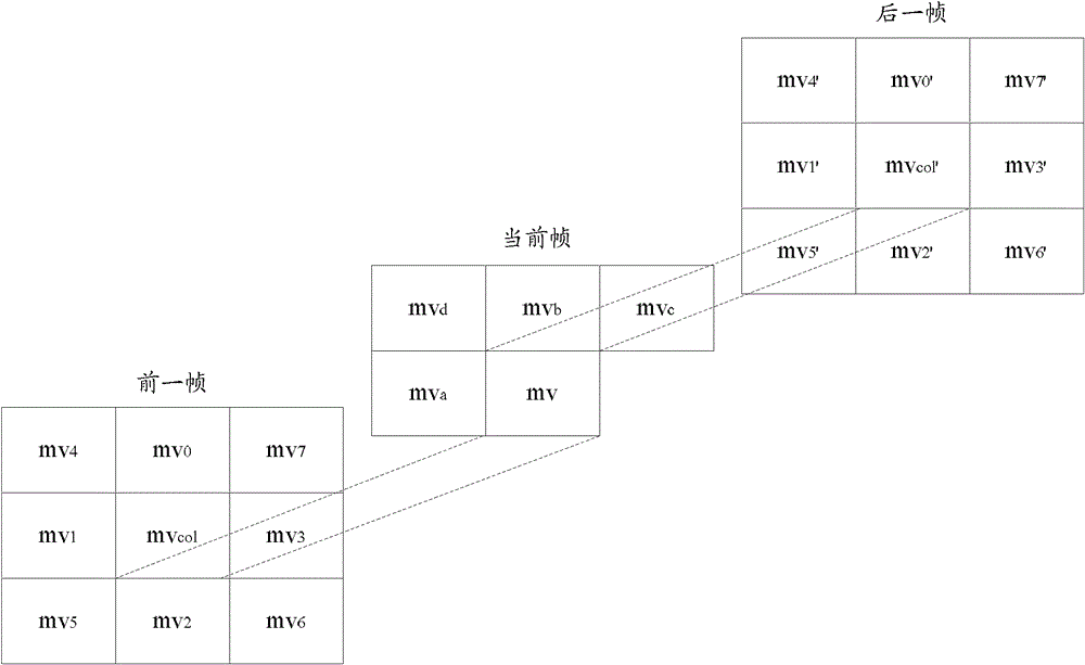
[0046] see Figure 1B , a schematic diagram for motion vector selection of a decoded block in a B-frame with bidirectional motion compensation properties. Assuming that the decoding block ...


PUM


Abstract

A video decoding method and encoding method, and a terminal. The decoding method comprises: acquiring an initial candidate motion vector set of a current block under decoding; removing candidate motion vectors not complying with a preset condition from the initial candidate motion vector set, and forming a new candidate motion vector set by use of remaining candidate motion vectors in the initial candidate motion vector set; and performing decoding according to the new candidate motion vector set. In the embodiment of the present application, some motion vectors can be removed, according to the preset condition, from the candidate motion vector set. On the condition that the number of the candidate motion vectors is decreased, the amount of information of reconstructed pixels in a reference frame obtained according to each candidate motion vector is decreased accordingly. Meanwhile, these candidate motion vectors are adjacent to each other, and selected reference blocks overlap each other, so that the reference blocks can be reused. As a result, the frequency of memory reading is decreased, hardware design is simplified, and encoding / decoding performance is improved.

Description

technical field [0001] The present application relates to the field of communication technologies, and in particular, to a video decoding method, an encoding method and a terminal. Background technique [0002] Motion prediction and motion compensation are important technologies in video compression. Part of the bits in the video compression code stream are used to transmit motion vector information, especially in the case of low bit rates. The bits usually exceed 50% of the total bits of the code stream. For the video coding of continuous dynamic images, several consecutive images are divided into three types: P, B, and I. Taking B frame as an example, it is based on the difference between the data of the adjacent previous frame, this frame, and the next frame. Compressing the current frame, that is, the B frame can obtain a motion vector set according to its previous frame and the next frame. Therefore, in order to improve the coding efficiency, in the prior art, the mot...

Claims


Application Information

Patent Timeline
Patent Type & Authority Patents(China)
IPC IPC(8): H04N19/513
CPCH04N19/52H04N19/56H04N19/61
Inventor 杨名远林四新宋锦
Owner HUAWEI TECH CO LTD
Features
  • R&D
  • Intellectual Property
  • Life Sciences
  • Materials
  • Tech Scout
  • Unparalleled Data Quality
  • Higher Quality Content
  • 60% Fewer Hallucinations
Learn More