
Detection method for spot target on satellite

A detection method and point target technology, which is applied in the direction of instruments, character and pattern recognition, computer components, etc., can solve the problems of not considering the time and space oversampling characteristics, so as to reduce the target extraction time, improve the target detection ability, improve The effect of early warning response capabilities

Active Publication Date: 2014-02-19
BEIJING RES INST OF SPATIAL MECHANICAL & ELECTRICAL TECH
View PDF3 Cites 0 Cited by
  • Summary
  • Abstract
  • Description
  • Claims
  • Application Information

AI Technical Summary

Problems solved by technology

[0007] However, due to the limitation of the detector technology level, the above algorithm does not consider the temporal and spatial oversampling characteristics

Method used


Image

  • Detection method for spot target on satellite
  • Detection method for spot target on satellite

Examples


Embodiment Construction

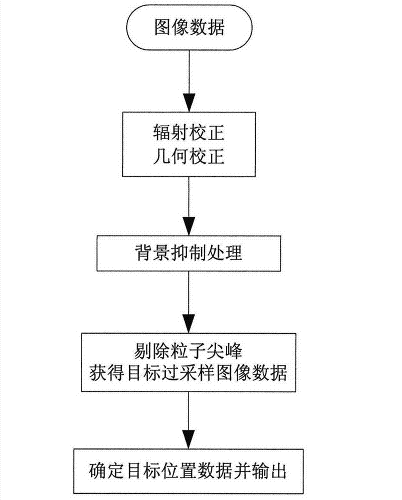
[0032] Below is the combination figure 2 The flow diagram shown further describes the invention.

[0033] Step 1: Perform radiation correction processing on the obtained image data by using the non-uniform correction coefficient of the TDI CCD, and perform geometric correction processing on the radiation-corrected image data. The image data is obtained by oversampling the image signal obtained by the TDI CCD.

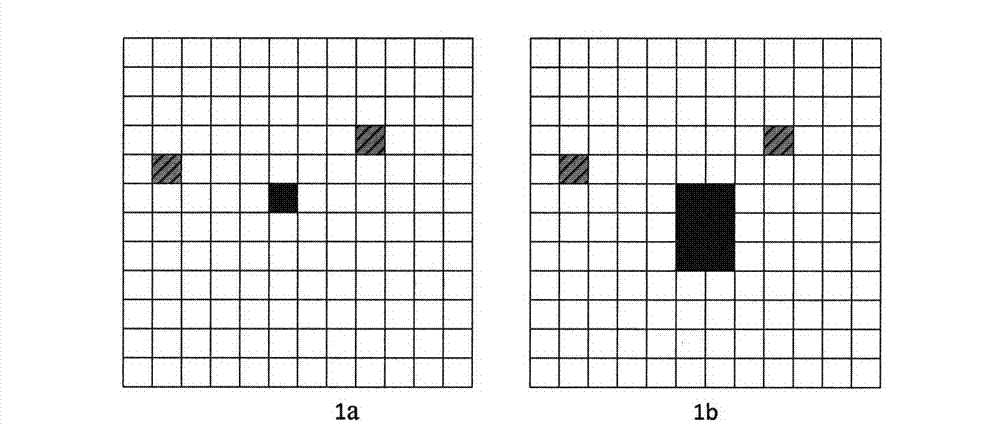
[0034] The on-board payload detects long-distance point targets using the traditional single-array, conventional sampling scanning imaging method. The target is a bright spot covering a single pixel on the image. If there is noise in some pixels on the focal plane of the detector, there will also be bright spots of a single pixel on the image caused by the noise, such as figure 1 as shown in a. Therefore, only through the correlation analysis of multiple frames of images, according to the amplitude changes and motion characteristics of the bright spots on the image,...


PUM


Abstract

The invention discloses a detection method for spot target on a satellite, the method comprises: a step of radiation correction and geometric rectification processing of image data, a step of acquiring target image data by background suppression processing of the image data, a step of acquiring target oversampling image data by eliminating particle peaks in the target image data, and a step of acquiring target position data by utilizing the target oversampling image data. The detection method of the invention assists in realization of detection of image data and acquirement of target on a satellite.

Description

technical field [0001] The invention relates to a point target detection method on a star. Background technique [0002] In the field of aerospace infrared early warning detection, because the detector is far away from the target (for example, the detection distance of a large elliptical orbit is tens of thousands of kilometers), the obtained target image is point-shaped, the target signal strength is very weak, and the image signal-to-noise ratio is low. Early warning detection is a weak point detection problem. [0003] Infrared radiation from clouds in the atmosphere, interference from the ground, terrain, and buildings are not only strong, but also have a strong spatial structure, which brings great difficulties to target detection. Due to the complexity of the background image and noise image and the image quality The low signal-to-noise ratio brings great difficulties to target detection. Due to the limitation of processing capacity, the current technology only perfo...

Claims


Application Information

Patent Timeline
Patent Type & Authority Patents(China)
IPC IPC(8): G06K9/32
Inventor 邢坤周峰吴立民刘兆军张涛张寅生胡斌王斌
Owner BEIJING RES INST OF SPATIAL MECHANICAL & ELECTRICAL TECH
Learn More