Supercharge Your Innovation With Domain-Expert AI Agents!

Gear set

A technology of gear sets and gears, applied in the field of gear sets, can solve problems such as unbalanced load

Active Publication Date: 2015-04-15
SMART MFG TECH
View PDF5 Cites 0 Cited by
  • Summary
  • Abstract
  • Description
  • Claims
  • Application Information

AI Technical Summary

Problems solved by technology

Although in principle additional layshafts could result in a further size reduction, the load sharing technique described above using a pair of helical gears with opposite helical teeth cannot be used for more than two layshafts because of the increased connection to the input helical gear 22 , 23, the other countershaft will not be able to balance the load between this shaft and other shafts connected to the same gear
Furthermore, the addition of an additional layshaft connected through a separate helical gear would not allow this shaft to be balanced with either of the existing layshafts 26, 28

Method used


Image

  • Gear set
  • Gear set
  • Gear set

Examples


Embodiment Construction

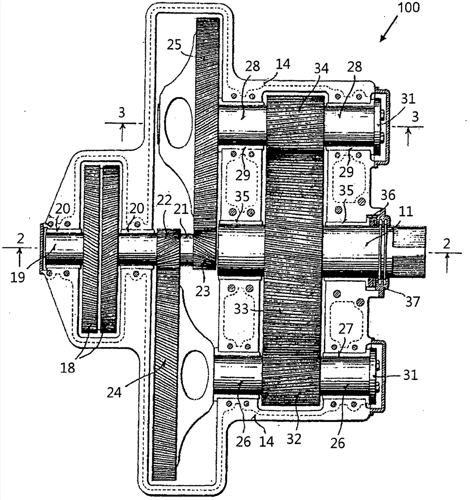
[0057] figure 1 The existing gear set of patent document US1759689 is described, which has been described in the background of the invention above.

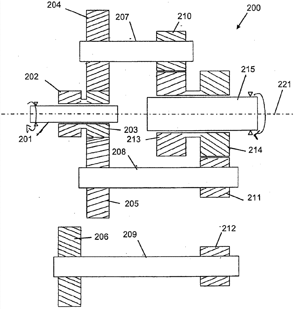
[0058] figure 2 Shown is a gear set 200 having three layshafts 207 , 208 , 209 . Each layshaft has an input gear 204 , 205 , 206 which meshes with one of a pair of helical input gears 202 , 203 mounted on the input shaft 201 . The pair of helical input gears 202 , 203 are configured to rotate together with the input shaft 201 . The helical input gears 202, 203 are fixed relative to each other, for example by being formed as a single unit, but mounted so as to allow some axial movement of the pair of gears. This is achieved by helical input gears 202 , 203 slidable along an axis 221 of the input shaft 201 , which preferably coincides with the axis of the output shaft 215 of the gear set 200 .

[0059] Each of the layshafts 207 , 208 , 209 also has an output gear 210 , 211 , 212 which meshes with one of a pair of helical outpu...


PUM


Abstract

A gear set 200 comprises an input shaft 201, an output shaft 215 and two or more pairs of helical gears 202, 203, 213, 214 of opposite hand Each pair of gears 202, 203, 213, 214 are fixed relative to each other but axially moveable in tandem and mounted on the input shaft 201 and / or the output shaft 215. Three or more lay shafts 207, 208, 209 each having an input gear 204, 205, 206 engaged with one of the pairs of helical gears 202, 203 and an output gear 210, 211, 212 engaged with one of the other helical gears 213, 214 on the output shaft 215 for transmitting rotational movement from the input shaft 201 to the output shaft 215. In operation an imbalance in load sharing between the lay shafts 207,208,209 results in axial movement of the pairs of helical gears 202, 203, 213, 214 tending to reduce the imbalance.

Description

technical field [0001] The present invention relates to a gear set for converting torque and speed of a rotating power source, in particular, to a gear set with a plurality of lay shafts for load distribution. Background technique [0002] In order to reduce the size and weight of the gearbox, it is known to transmit the load via multiple layshafts (also known as layshafts or layshafts) rather than one larger layshaft. This allows for a reduction in the overall size of the gearbox as the load can be transmitted more efficiently through two smaller shafts rather than one larger shaft. However, the downside of gearing is that it can cause one gear to mesh before the others, resulting in a larger percentage of the load being borne by a single layshaft. This necessitates an increased safety factor in the design of the secondary shaft, reducing the advantage of using such multiple shafts. [0003] For two layshafts, it is possible to ensure an even load distribution between the...

Claims


Application Information

Patent Timeline
Patent Type & Authority Patents(China)
IPC IPC(8): F16H1/22
CPCF16H1/22
Inventor 周长秀
Owner SMART MFG TECH
Features
  • R&D
  • Intellectual Property
  • Life Sciences
  • Materials
  • Tech Scout
  • Unparalleled Data Quality
  • Higher Quality Content
  • 60% Fewer Hallucinations
Learn More