Control wire driving mechanism for use in endoscope

a technology of endoscope and driving mechanism, which is applied in the field of endoscope control wire driving mechanism, can solve the problems of inability to ensure a sufficient length for the grip portion of the control part, inability to ensure a sufficient length, and inability to operate. the maximum angle of rotation is considerably limited

Inactive Publication Date: 2002-08-27
ASAHI KOGAKU KOGYO KK
View PDF12 Cites 262 Cited by
  • Summary
  • Abstract
  • Description
  • Claims
  • Application Information

AI Technical Summary

Problems solved by technology

However, such a rack-and-pinion mechanism needs a space for travel of the rack on each of the front and rear sides of the pinion as viewed in the axial direction of the control wire.
Consequently, it is impossible to ensure a sufficient length for the grip portion of the control part.
This causes operability to be impaired.
Therefore, the maximum angle of rotation is limited considerably, and the control wire is likely to break owing to the stress concentration on the secured portion of the control wire.
Howe

Method used


Image

  • Control wire driving mechanism for use in endoscope
  • Control wire driving mechanism for use in endoscope
  • Control wire driving mechanism for use in endoscope

Examples


Embodiment Construction

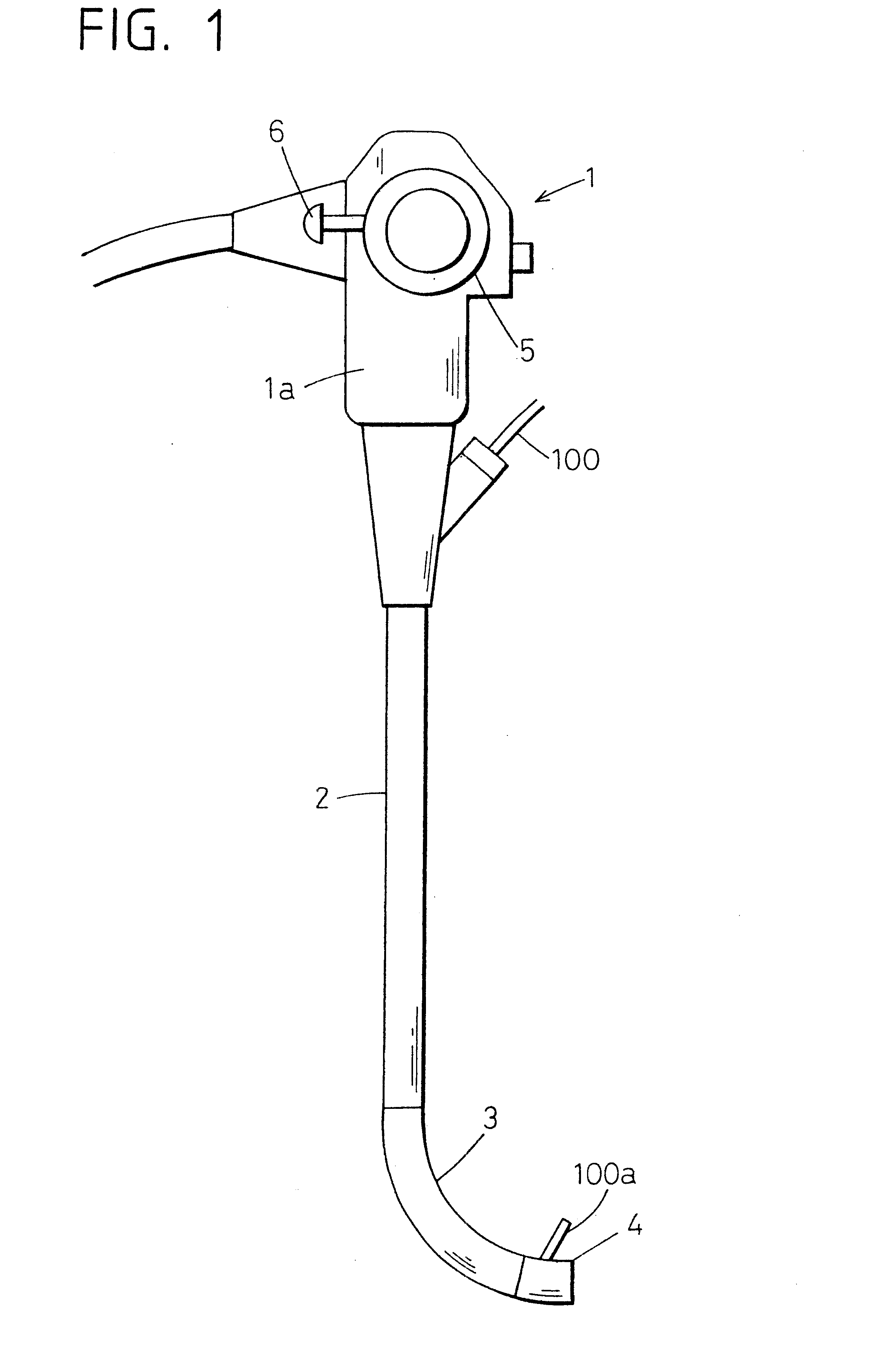
FIG. 1 shows the whole arrangement of an endoscope.

The endoscope has a control part 1 adapted to be held by an operator with his / her hand when operating the endoscope.

A flexible tube 2 is connected to the lower end of the control part 1 to form an insert part of the endoscope.

A bendable portion 3 is connected to the distal end of the flexible tube 2. The bendable portion 3 can be bent as desired by remote control. A distal end block 4 is connected to the distal end of the bendable portion 3. The distal end block 4 contains an objective optical system or the like.

A bending control knob 5 is provided on the upper half of the control part 1 to control bending of the bendable portion 3. A portion of the control part 1 below the bending control knob 5 is a grip portion 1a. An erecting member control lever 6 is used to change remotely the direction of projection of a distal end portion 10a of a treating instrument 100 inserted into an instrument-inserting channel of the endoscope.
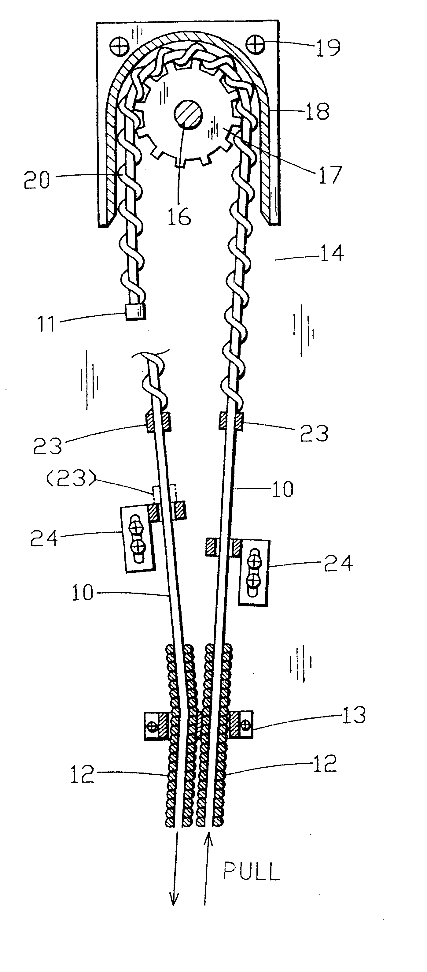
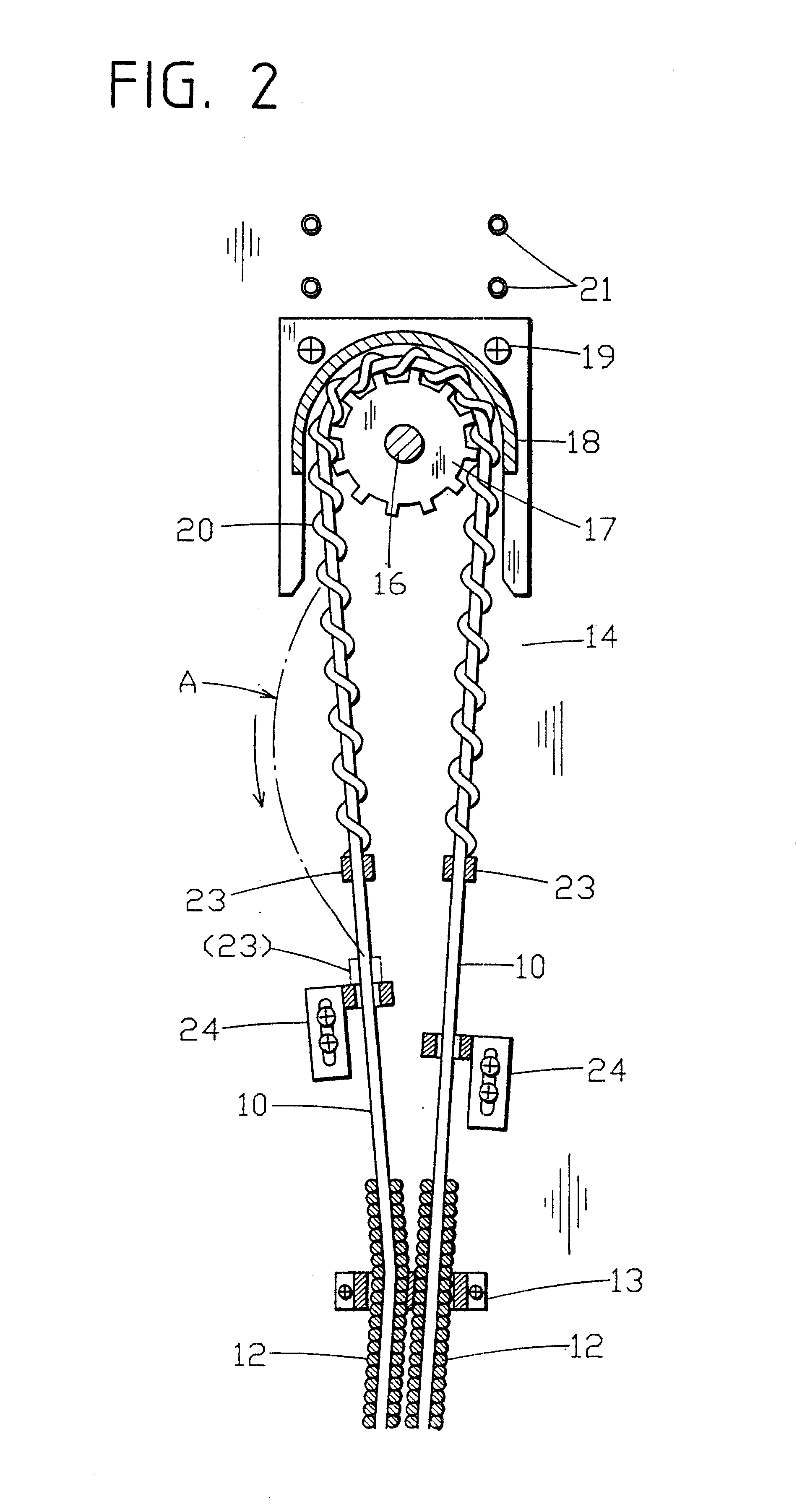
FIG. 2 s...


PUM


Abstract

A control wire driving mechanism for use in an endoscope includes a toothed wheel actuated to rotate in a control part of the endoscope. A control wire has a cord-like member helically wound on and secured to the outer peripheral surface of a portion near the proximal end thereof at a pitch corresponding to the pitch of the toothed wheel. The control wire is meshed with the toothed wheel at the portion wound with the cord-like member.

Description

The present disclosure relates to subject matter contained in Japanese Patent Application No. 11-319134 (filed on Nov. 10, 1999) and Japanese Patent Application No. 2000-50666 (filed on Feb. 28, 2000), which are expressly incorporated herein by reference in their entireties.1. Field of the InventionThe present invention relates to a control wire driving mechanism for use in an endoscope to pull a control wire by rotation of a rotating member.2. Description of the Prior ArtThere has heretofore been known a control wire driving mechanism for use in a bending control device of an endoscope, for example. In the mechanism, a pinion (i.e. a toothed wheel) that is actuated to rotate with a control knob (or a control lever) is meshed with a rack connected to the proximal end of a control wire, and the rack is advanced or retracted linearly by rotating the pinion, thereby driving the control wire to advance or retract.However, such a rack-and-pinion mechanism needs a space for travel of the ...

Claims


Application Information

Patent Timeline
IPC IPC(8): A61B1/00A61B1/005
CPCA61B1/00098A61B1/00188A61B1/0052A61B1/0057
Inventor OUCHI, TERUO
Owner ASAHI KOGAKU KOGYO KK
Why Eureka
Try Eureka