Pinion Blade Drive Mechanism for a Laparoscopic Vessel Dissector

a technology of laparoscopic vessel and drive mechanism, which is applied in the field of laparoscopic vessel dissector apparatus, can solve the problems of affecting the operation of the operator, prone to present difficulties in transecting sealed tissue, and longer strokes may prove awkward or cumbersome for the operator

Inactive Publication Date: 2011-11-10
TYCO HEALTHCARE GRP LP
View PDF7 Cites 263 Cited by
  • Summary
  • Abstract
  • Description
  • Claims
  • Application Information

AI Technical Summary

Benefits of technology

[0010]According to another aspect of the disclosure, an electrosurgical instrument includes a handle assembly including an actuator mounted for manipulation through an actuation stroke. An elongate shaft extends distally from the handle assembly and defines a longitudinal axis. An end effector extends distally from the elongate shaft. The end effector includes a pair of jaw members wherein at least one jaw member is configured to move between an open position substantially spaced from the other of the pair of jaw members and a closed position wherein the jaw members are closer together. The pair of jaw members includes at least one

Problems solved by technology

Longer jaws, however, may tend to present difficulties in transecting the seale

Method used


Image

  • Pinion Blade Drive Mechanism for a Laparoscopic Vessel Dissector
  • Pinion Blade Drive Mechanism for a Laparoscopic Vessel Dissector
  • Pinion Blade Drive Mechanism for a Laparoscopic Vessel Dissector

Examples


Embodiment Construction

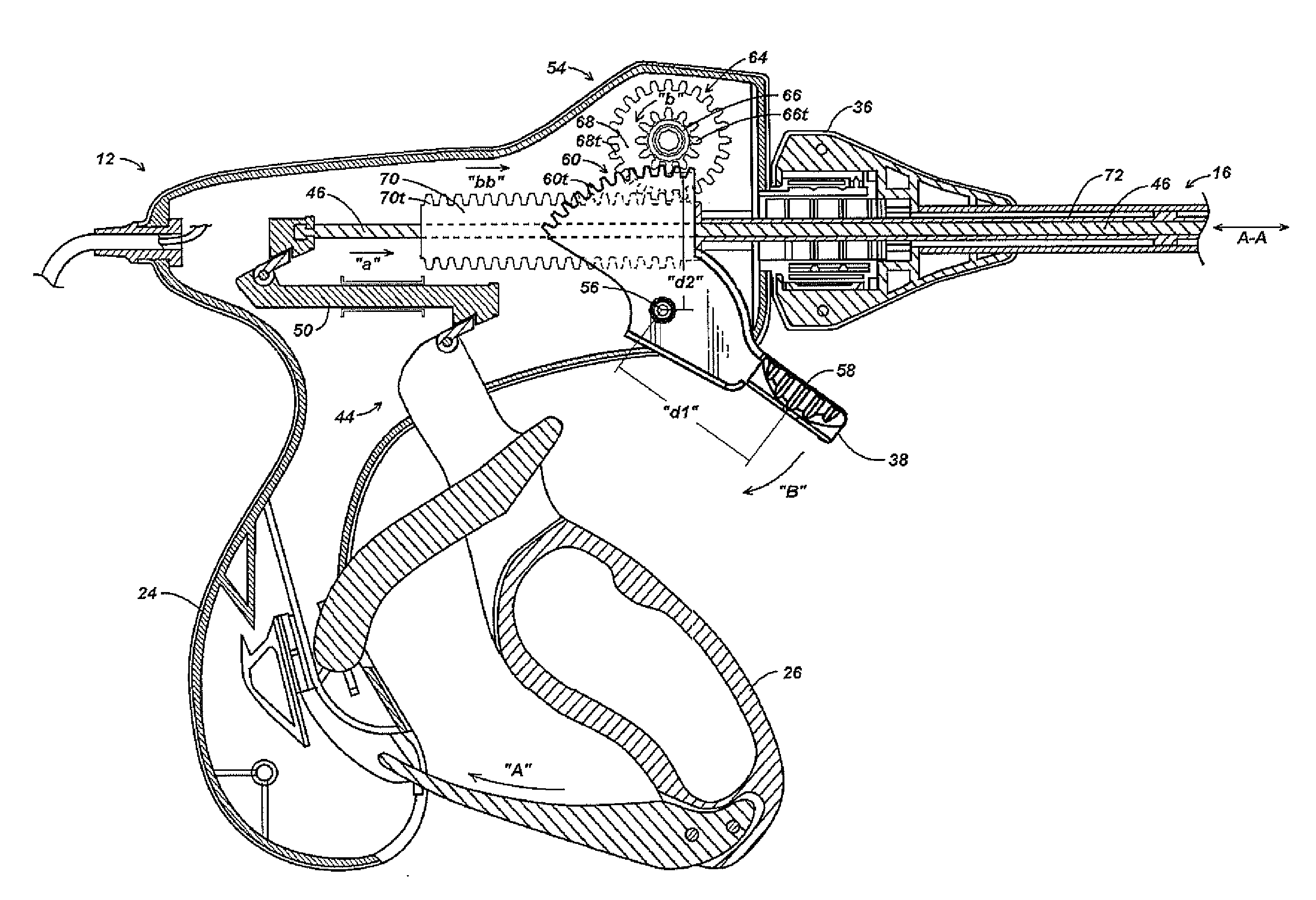
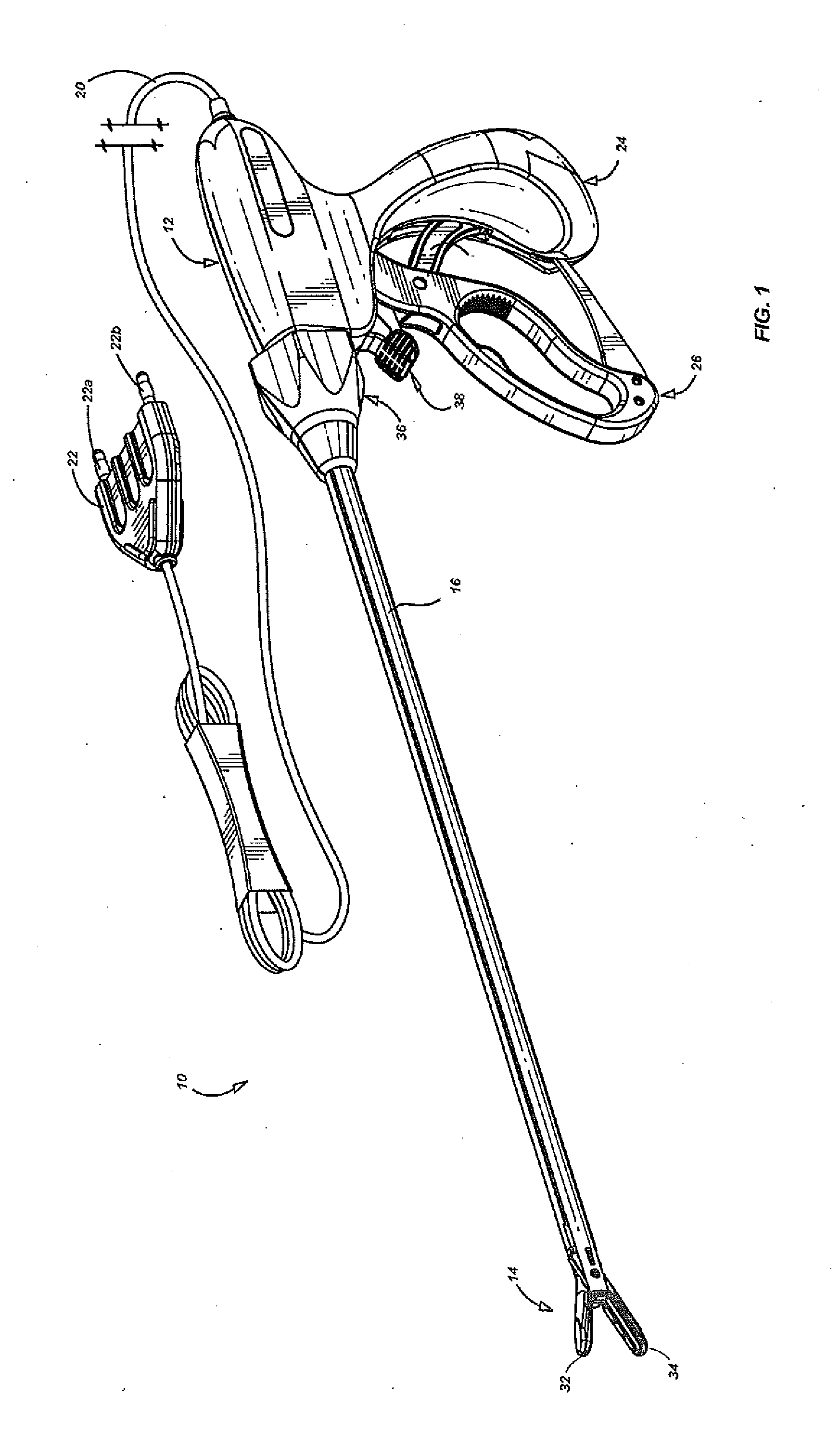
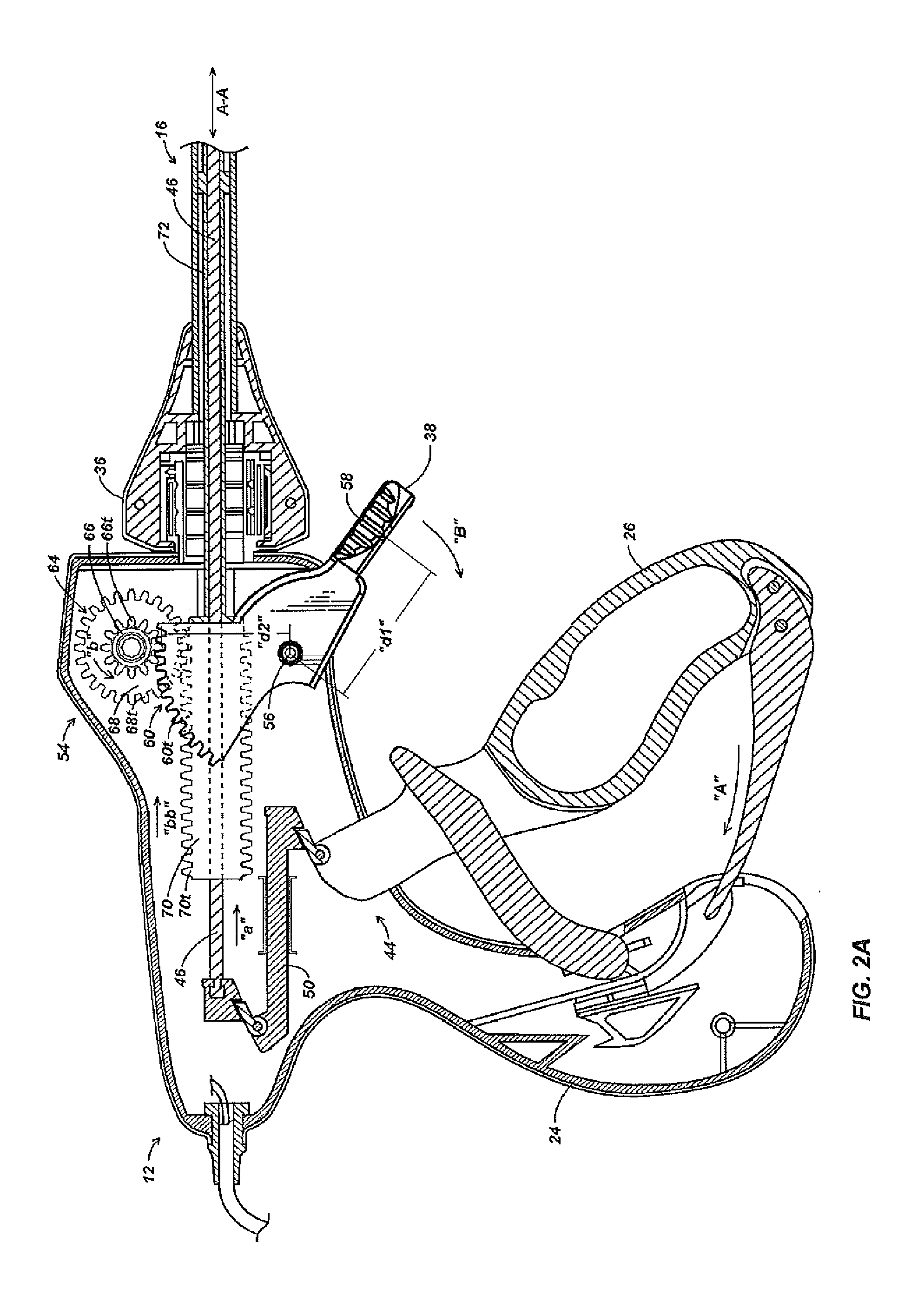
[0020]Referring initially to FIG. 1, an embodiment of an electrosurgical instrument is depicted generally as 10. The instrument 10 includes a handle assembly 12 for remotely controlling an end effector 14 through an elongate shaft 16. Although this configuration is typically associated with instruments for use in endoscopic surgical procedures, various aspects of the present disclosure may be practiced in connection with traditional open procedures as well.

[0021]Handle assembly 12 is coupled to an electrosurgical cable 20, which may be used to connect the instrument 10 to a source of electrosurgical energy. The cable 20 extends to connector 22 including prong members 22a and 22b that are dimensioned to mechanically and electrically connect the instrument 10 to an electrosurgical generator (not shown). Each of the two prong members 22a and 22b may be associated with an opposite electrical terminal or potential (supplied by the generator) such that bipolar energy may be conducted thro...


PUM


Abstract

A surgical instrument comprises a handle assembly including an actuator mounted for manipulation through an actuation stroke. An elongate shaft extends distally from the handle assembly and defines a longitudinal axis. A reciprocating member extends at least partially through the elongate shaft, and is mounted for longitudinal motion through the elongate shaft in response to manipulation of the actuator through the actuation stroke. A drive mechanism includes a first rotating component coupled to the actuator about a first circumference to induce rotational motion in the first rotating component. A second rotating component is coupled to the first rotating component such that rotational motion in the first rotating component induces rotational motion in the second rotating component. The second rotating component is coupled to the reciprocating member about a second circumference such that rotational motion of the second rotating component induces longitudinal motion in the reciprocating member. The second circumference is greater than the first circumference.

Description

BACKGROUND[0001]1. Technical Field[0002]The present disclosure relates to an apparatus for joining and transecting tissue. In particular, the disclosure relates to an apparatus having a drive mechanism for advancing a blade through tissue.[0003]2. Background of Related Art[0004]Instruments such as electrosurgical forceps are commonly used in open and endoscopic surgical procedures to coagulate, cauterize and seal tissue. Such forceps typically include a pair of jaws that can be controlled by a surgeon to grasp targeted tissue, such as, e.g., a blood vessel. The jaws may be approximated to apply a mechanical clamping force to the tissue, and are associated with at least one electrode to permit the delivery of electrosurgical energy to the tissue. The combination of the mechanical clamping force and the electrosurgical energy has been demonstrated to join adjacent layers of tissue captured between the jaws. When the adjacent layers of tissue include the walls of a blood vessel, sealin...

Claims


Application Information

Patent Timeline
IPC IPC(8): A61B18/18
CPCA61B17/295A61B18/1402A61B2018/1455A61B2017/2923A61B2018/1412A61B18/1445
Inventor GERHARDT, THOMAS J.
Owner TYCO HEALTHCARE GRP LP
Why Eureka
Try Eureka