
Milk foam kettle

A milk foam and cup technology, applied in the field of milk foam pots, can solve the problems of increased weight, water inflow of the working circuit, high sealing requirements of the shaft sleeve and the heating element, etc., and achieve the effect of enhancing the taste

Active Publication Date: 2014-09-03
YUYAO SUNBOY ELECTRIC APPLIANCE
View PDF5 Cites 0 Cited by
  • Summary
  • Abstract
  • Description
  • Claims
  • Application Information

AI Technical Summary

Problems solved by technology

[0002] There are various milk froth pots on the market now, and some stirrers are connected with a drive motor on the pot lid, which needs to be connected with a longer stirring arm to penetrate into the pot body, which is not easy to clean, and the pot lid taken out after work is difficult to place , the inverted pot lid is easy to make the milk flow into the motor bearing along the stirring arm, causing the motor shaft and the bearing to bond. The stirring shaft and the pot lid are not easy to clean. The machine vibrates and makes a lot of noise when it is working, and it cannot even be used normally
Another example is another milk frothing pot (notification number is CN201033032Y, the patent fixes the drive motor on the bottom of the pot through a bracket, and the output shaft of the drive motor is installed in the heating element at the bottom of the pot through a bushing and extends into the output of the drive motor. The shaft extends into the body of the milk foaming pot), the above two types of milk foaming pots have higher requirements on the sealing of the shaft sleeve and the heating element, not only to prevent the lubricant of the drive motor from entering the pot body, but also to prevent the milk in the pot body Penetrating into the bottom of the pot, affecting the working circuit of the bottom of the pot, serious may cause safety accidents
At the same time, the milk froth pot is connected with the driving device, heating device, and working circuit. It cannot be separated, which increases the weight and brings inconvenience to the milk froth. Moreover, it is easy to cause water to enter the working circuit during cleaning, and it cannot be directly put into the dishwasher. Internal cleaning

Method used


Image

  • Milk foam kettle
  • Milk foam kettle
  • Milk foam kettle

Examples


Embodiment 1

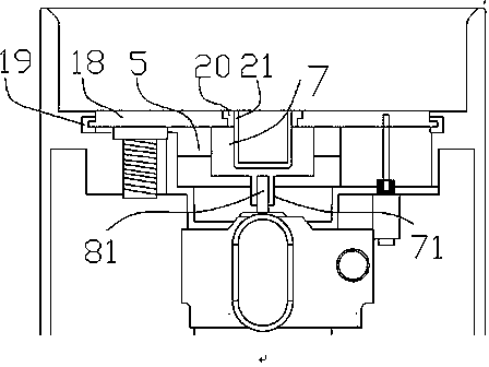
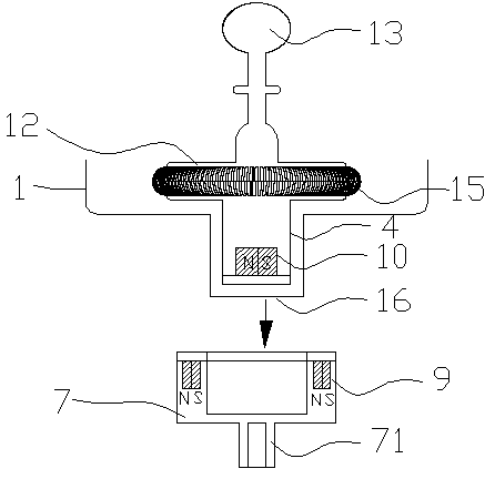
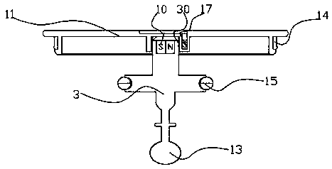
[0026] A milk frothing jug includes a cup body 1 and a base 2, and a cup cover 11 is provided above the cup body 1. The cup body 1 and the base 2 are independent parts, and the two can be separated; the cup body 1 can be placed on the base 2 arbitrarily at 360 degrees. The cup body 1 can be separated from the base 2 without destroying or disassembling, the cup body 1 can be taken out from the base 2, and the cup body 1 and the base 2 can be cleaned, maintained and replaced separately.

[0027] The bottom of the cup body 1 is provided with a stirrer 3 and a positioning sleeve 16; Among them, a driving device 7 for driving the stirrer 3 to rotate is provided below the heating element 5 , and the driving device 7 is connected with a driving motor 8 . The driving device 7 is driven by the output shaft 81 of the driving motor 8 , the output shaft 81 is connected with the joint 71 of the driving device 7 , and the driving motor 8 is installed on the base 2 . In order to facilitate...


PUM


Abstract

The invention relates to household appliances, in particular to a milk froth pot for heating, foaming and stirring liquid food. A milk frothing pot, comprising a cup body and a base, the cup body is provided with a stirrer and a positioning sleeve, the base is provided with a heating element, a heat conducting plate and a fixing sleeve, and the positioning sleeve is inserted into the In the fixed sleeve, a driving device for driving the agitator to rotate is provided under the heating element, and the driving device is connected with a driving motor. The invention utilizes the principle of magnetic force to completely separate the upper cup body containing the milk from the working circuit, heating device and driving device of the driving stirring device. When in use, the milk will not seep into the base and affect the circuit, and the lubricant of the motor will not enter. It is hygienic and safe to pollute the cup body and dirty the milk; the poles of the driving magnet and the driven magnet are set horizontally, which saves space, and the agitator is driven by magnetic force, which is safe and hygienic. The agitator is only positioned on the cup body , making it easier to disassemble and clean the agitator.

Description

technical field [0001] The invention relates to household appliances, in particular to a milk froth pot for heating, foaming and stirring liquid food. Background technique [0002] There are various milk froth pots on the market now, and some stirrers are connected with a drive motor on the pot lid, which needs to be connected with a longer stirring arm to penetrate into the pot body, which is not easy to clean, and the pot lid taken out after work is difficult to place , the inverted pot lid is easy to make the milk flow into the motor bearing along the stirring arm, causing the motor shaft and the bearing to bond. The stirring shaft and the pot lid are not easy to clean. The machine vibrates and makes a lot of noise when it is working, and it cannot even be used normally. Another example is another milk frothing pot (notification number is CN201033032Y, the patent fixes the drive motor on the bottom of the pot through a bracket, and the output shaft of the drive motor is ...

Claims


Application Information

Patent Timeline
Patent Type & Authority Patents(China)
IPC IPC(8): A47J43/046
CPCA47J27/004A47J43/046A47J43/0465
Inventor 俞春平
Owner YUYAO SUNBOY ELECTRIC APPLIANCE
Learn More