
Method for calculating water discharge amount and water discharge time during dynamic water fall process in submersible partially penetrating well or well group

A non-intact well and calculation method technology, applied in the direction of measuring devices, measuring flow/mass flow, liquid/fluid solid measurement, etc., can solve problems such as inability to meet project construction precipitation, project duration, and cost impact

Active Publication Date: 2014-09-17
CENT SOUTH UNIV
View PDF1 Cites 0 Cited by
  • Summary
  • Abstract
  • Description
  • Claims
  • Application Information

AI Technical Summary

Problems solved by technology

However, there is no relevant calculation method at home and abroad for the daily precipitation and the time required for precipitation in the process of water level drop or recovery in the process of dewatering of uncompleted wells or well groups under pressure during engineering construction. On the basis of trial pumping, we will continue to adjust and finally determine the specific displacement, which will have a certain impact on the construction period and cost of the project.
[0004] Generally speaking, the daily precipitation during the dewatering process of pressure-bearing incomplete wells or well groups during engineering construction depends on the experience of engineering and technical personnel, and cannot meet the requirements of engineering construction dewatering.

Method used


Image

  • Method for calculating water discharge amount and water discharge time during dynamic water fall process in submersible partially penetrating well or well group
  • Method for calculating water discharge amount and water discharge time during dynamic water fall process in submersible partially penetrating well or well group
  • Method for calculating water discharge amount and water discharge time during dynamic water fall process in submersible partially penetrating well or well group

Examples


Embodiment Construction

[0042] (1) Calculation method of drainage volume and drainage time in the process of single well water level drop

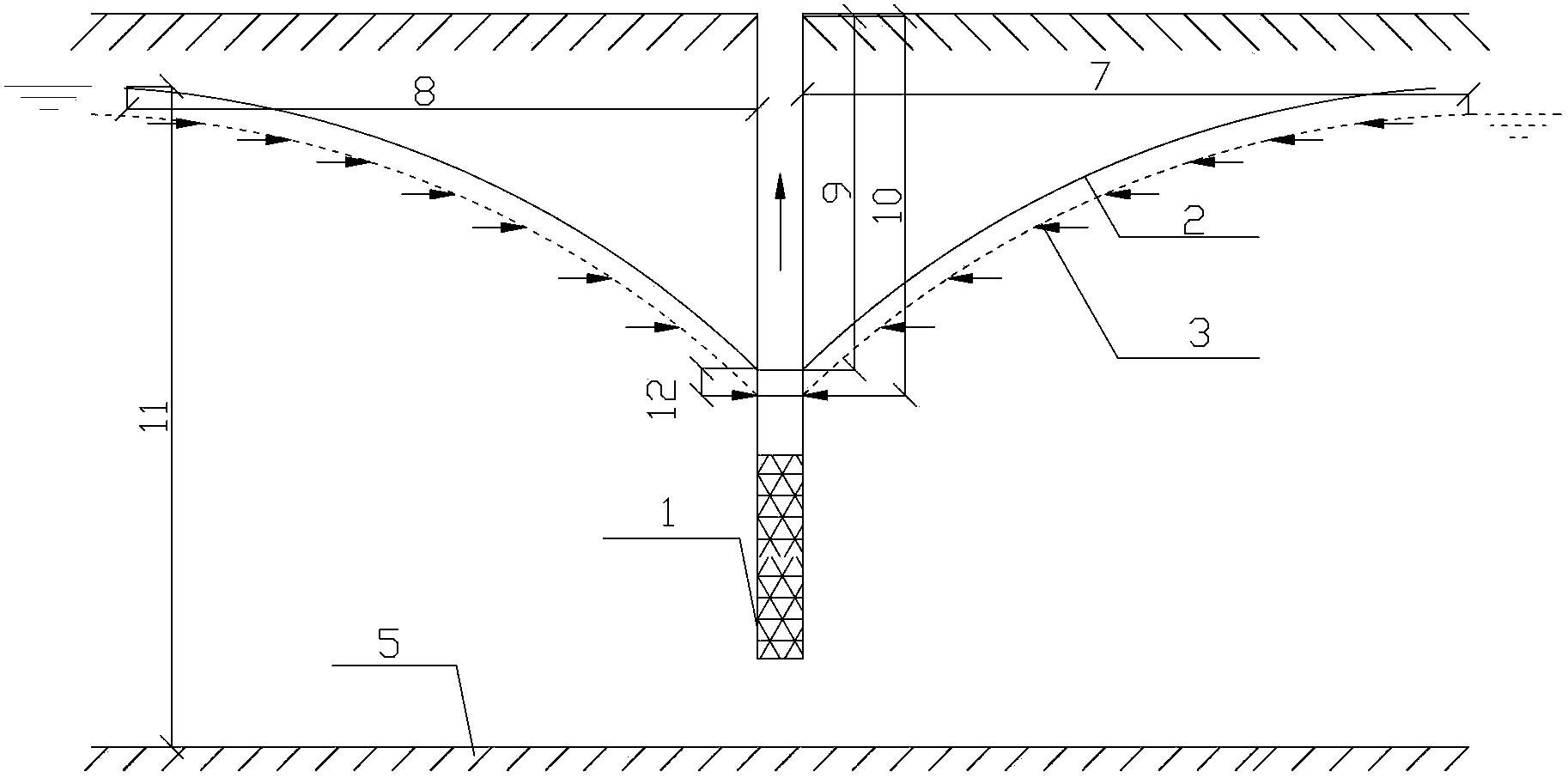
[0043] Firstly, a single well was taken for analysis. figure 1 It is a schematic diagram of the single well precipitation funnel curve of the present invention, as figure 1 As shown, after the precipitation, a precipitation funnel curve is formed around the well. Since the groundwater around the precipitation well is continuously replenished into the precipitation area, in order to ensure that the water level in the well is maintained at a certain stable water level S 1 , it is necessary to maintain a stable displacement Q(S 1 ), the precipitation funnel curve at this time is X 1 , when it is further necessary to reduce the water level in the well to S 2 , the precipitation funnel curve X is formed 2 , at this time, it is necessary to maintain the original stable displacement Q(S 1 ) on the basis of adding the displacement in the well, that is, increasing th...


PUM


Abstract

The invention discloses a method for calculating water discharge amount and water discharge time during a dynamic water fall process in a submersible partially penetrating well or a well group. From a basic theory and a basic rule of seepage of underground water, on the basis of an everyday water discharge amount calculation formula under the condition of retaining a stable water level during the water fall process in the pressure-bearing partially penetrating well and the well group, the specific method for calculating the water discharge amount and the water discharge time in a process that the underground water level in the pressure-bearing partially penetrating well or the well group is changed from an initial water level to a target water level is implemented. By using the method, the situation that the calculation of the water discharge amount depends on experience for a long time in a water level change stage during the design of the pressure-bearing partially penetrating well or the well group at the present is changed; and the calculation and the dynamic control for the water discharge amount in the full water fall process of the pressure-bearing partially penetrating well or the well group in engineering construction are realized.

Description

technical field [0001] The invention relates to a calculation method suitable for engineering construction dewatering and drainage, in particular to a calculation method for dewatering and drainage time in the process of dynamic dewatering of submerged incomplete wells or well groups. Background technique [0002] The purpose of foundation pit dewatering is to reduce the groundwater level below a certain depth requirement, which can satisfy the construction of the foundation pit structure without water interference, thereby reducing the difficulty of construction, and ensuring the excavation and structure of the foundation pit to the greatest extent. construction safety. [0003] At present, a lot of research has been done on the daily displacement when the precipitation is maintained at a certain stable water level at home and abroad. In terms of theory, according to the stable and unsteady seepage movement in the confined aquifer, the corresponding groundwater movement th...

Claims


Application Information

Patent Timeline
Patent Type & Authority Patents(China)
IPC IPC(8): G01F1/00
Inventor 施成华彭立敏邓之友罗晶杨伟超雷明锋丁祖德
Owner CENT SOUTH UNIV
Learn More