Supercharge Your Innovation With Domain-Expert AI Agents!

Apparatus for driving a gas discharge lamp

A technology of gas discharge lamps and arcs, which is applied in the use of gas discharge lamps, lighting devices, electric light sources, etc., and can solve problems such as shortening lamp life

Inactive Publication Date: 2012-09-26
KONINK PHILIPS ELECTRONICS NV
View PDF4 Cites 0 Cited by
  • Summary
  • Abstract
  • Description
  • Claims
  • Application Information

AI Technical Summary

Problems solved by technology

The vessel walls will stabilize the arc, but contact between the arc plasma and the vessel walls is undesirable as this may shorten lamp life

Method used


Image

  • Apparatus for driving a gas discharge lamp
  • Apparatus for driving a gas discharge lamp
  • Apparatus for driving a gas discharge lamp

Examples


Embodiment Construction

[0020] figure 1 is a block diagram schematically showing an exemplary embodiment of an electronic driver 10 for driving a gas discharge lamp L. As shown in FIG. The driver 10 has output terminals 7, 8 for receiving the lamp and for connecting to the lamp poles. The lamp L is of the type having two electrodes facing each other in a sealed chamber. In a particular embodiment, the lamp is a xenon discharge lamp for use in automobiles. During operation, a discharge is maintained in the chamber, which is indicated as an arc.

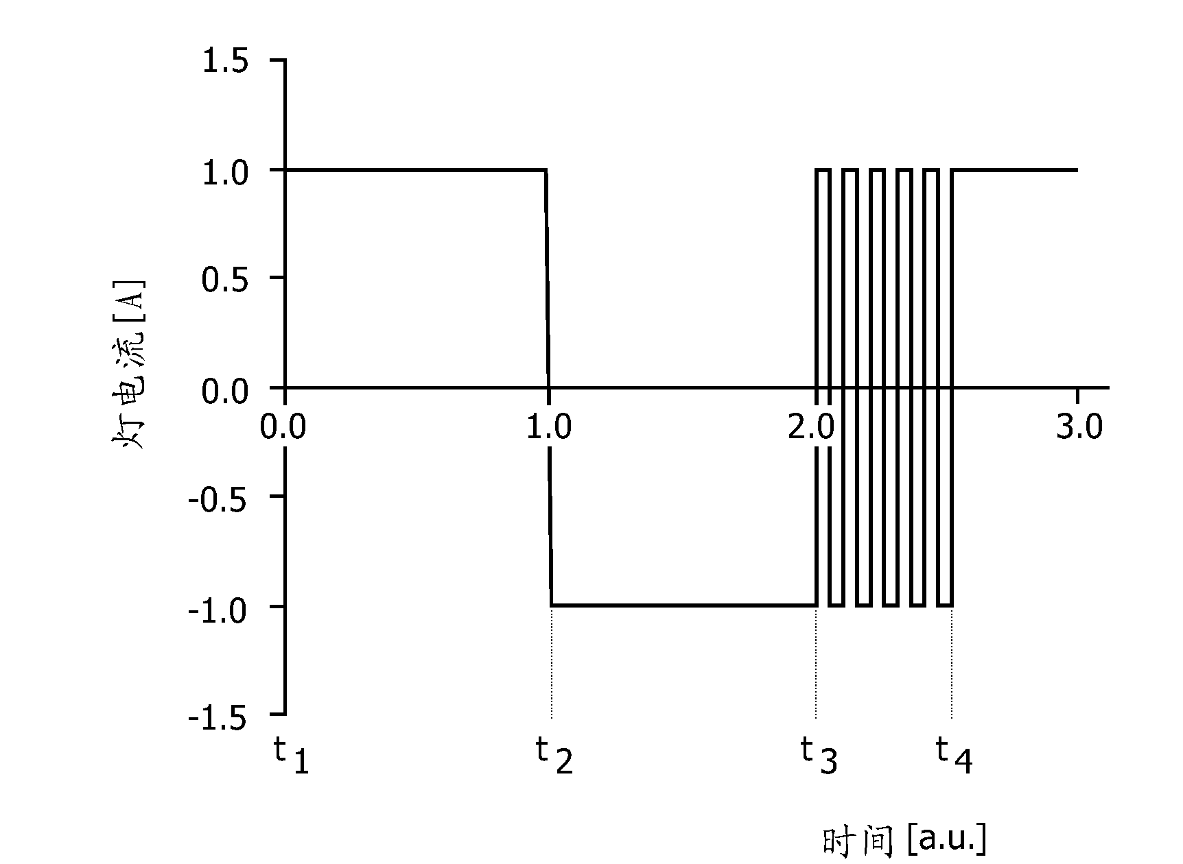
[0021] In the electronic lamp driver according to the invention, the current applied to the lamp can be regarded as comprising three mutually independent current components. For this reason, the following explanation diagrammatically assumes that the lamp driver comprises three functionally independent Current sources, the output terminals of which are coupled in parallel with the device output terminals 7, 8, such that the lamp L receives the sum of the t...


PUM


Abstract

A method of generating a measuring signal indicating arc straightness in a gas discharge lamp (L) comprises the following steps: in a first step, applying a first lamp current (IN) to the lamp; in a second step, adding a brief pulse current (Ip) to the first lamp current (IN), allowing the lamp voltage to regain a steady state, and measuring the resulting average value of the lamp voltage (V2) in this steady state; generating a measuring signal indicating arc straightness on the basis of said average lamp voltage (V2) measured in the second step.

Description

technical field [0001] The present invention relates generally to gas discharge lamps, and more particularly to high pressure or high intensity discharge lamps. Specifically, the invention relates to xenon lamps used in the automotive sector. Background technique [0002] Since gas discharge lamps are well known, their description will be kept concise. In general, such lamps consist of: a container (usually a quartz container) enclosing a chamber with a suitable filling; and two electrodes positioned opposite each other, passing through the wall of the container and extending into the chamber . With high voltage ignition, a fault may occur in the gas filling, causing plasma arcing between the two electrodes. The arc may take on a curved shape ("bending" of the arc) which is a problem. In vertical operation, bending may occur due to Lorentz forces of the lamp construction. When the lamp is in the horizontal position, ie when the arc is oriented horizontally (which is typ...

Claims


Application Information

Patent Timeline
Patent Type & Authority Applications(China)
IPC IPC(8): H05B41/292H05B41/392
CPCH05B41/2928H05B41/3928Y02B20/202Y02B20/00
Inventor E.T.M.德科宁B.西佩拉亚J.H.A.哈格拉亚L.达林豪森
Owner KONINK PHILIPS ELECTRONICS NV
Features
  • R&D
  • Intellectual Property
  • Life Sciences
  • Materials
  • Tech Scout
  • Unparalleled Data Quality
  • Higher Quality Content
  • 60% Fewer Hallucinations
Learn More