
All-round lighting windows

An all-round, window-based technology, applied to windows/doors, special equipment for doors/windows, building components, etc., can solve problems such as limited lighting effects, and achieve the effect of improving indoor lighting

Active Publication Date: 2015-09-02
JIANGSU HONGSHENG DECORATION ENG
View PDF7 Cites 0 Cited by
  • Summary
  • Abstract
  • Description
  • Claims
  • Application Information

AI Technical Summary

Problems solved by technology

It can be seen that even for windows facing south, the lighting effect is very limited.

Method used


Image

  • All-round lighting windows
  • All-round lighting windows
  • All-round lighting windows

Examples


Embodiment 1

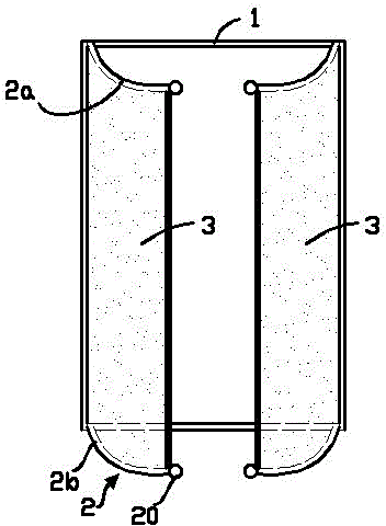
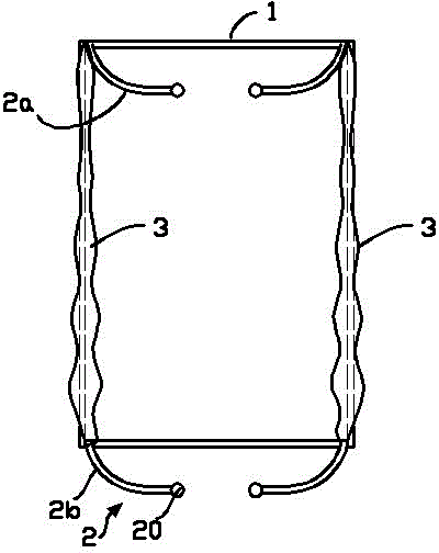
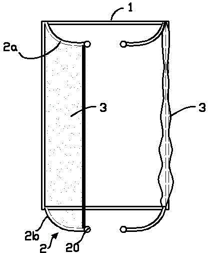
[0027] Various states of Embodiment 1 such as Figure 1~Figure 3 as shown, figure 1 Among them, the reflectors 3 on the left and right guide frames are all in an open state, which is usually not used, and is only used as a light-shielding function when the light is too strong; figure 2 Among them, the reflective parts 3 on the left and right guide frames are all folded. At this time, it is usually used when the sunlight is directly facing the window, and there is no need to use the reflective part 3 for light collection; image 3 Then it is the normal use state of Embodiment 1. At this time, the reflector 3 on one side of the window frame 1 is opened to reflect the light irradiated from the other side of the window frame 1, so that it shines into the room in the window frame, enhancing Room lighting effect.

[0028] Figure 7 Shown is the second embodiment of the omni-directional daylighting window. In this embodiment, the left and right guide frames are integrated to form...

Embodiment 3

[0031] Embodiment three: for embodiment three of the present invention, adopt the structure that left guide frame and right guide frame are separated in embodiment one, and make the radius of lower guide rail smaller than the radius of upper guide rail, this embodiment passes embodiment one, two The analysis can be done simply and will not be repeated here.

[0032] For the above-mentioned embodiments 1, 2, and 3, it is still possible to optimize and improve the parts they have in common. For example, for the edge tie rod, the bonding side of the edge tie rod and the window frame 1 can be made into a strip-shaped plane, and in There is a pair of magnetic strips or a magnetic strip and an iron strip on the relative bonding surface of the window frame and the edge tie rod. That is, a magnetic strip is attached to the edge tie rod and the window frame, or one is pasted with a magnetic strip, and the other is attached. One is affixed with an iron bar so that the edge pull rod can ...


PUM


Abstract

The invention provides an all-directional daylighting window, belonging to the field of building decoration facilities. The all-directional daylighting window comprises a window frame and window glass, wherein the window frame is provided with a guide frame which is in bilateral symmetry; the guide frame comprises an arc-shaped upper guide rail and an arc-shaped lower guide rail; the upper guide rail is arranged at a horizontal surface where the upper edge of the window frame is positioned; the lower guide rail is arranged at a horizontal surface where the lower edge of the window frame is positioned; and the arc concave openings of the upper guide rail and the lower guide rail face the central side of the window frame. The all-directional daylighting window also comprises a light reflection part, wherein the light reflection part comprises a light reflection curtain and edge pull rods at the two sides of the light reflection curtain; the upper end and the lower end of each edge pull rod are provided with guide-connection parts which can move along the upper guide rail and the lower guide rail; the upper edge and the lower edge of the light reflection curtain are provided with guide sleeves for sleeving the upper guide rail and the lower guide rail; and the inner side surface of the light reflection curtain is provided with a light reflection layer. With the all-directional daylighting window, a room can obtain an excellent daylighting effect at every time in the day.

Description

technical field [0001] The invention relates to the field of building decoration facilities, in particular to a window basic structure. Background technique [0002] In the process of housing architectural design, building lighting is an extremely important issue. With the rapid advancement of urbanization, due to the limitation of building space, building lighting can no longer be arbitrary. For buildings with unsatisfactory environments, some rooms Daylighting is even very difficult, which seriously affects the quality of the living or office environment. [0003] In fact, at present, in buildings, each room generally has a window facing south or north. For the windows facing south, usually only when it is close to noon, more light can be collected, and when it is far from noon, the light is very small. For hazy weather, good light can only be obtained at noon; for north-facing windows, the lighting effect is much weaker than that of south-facing windows. It can be seen ...

Claims


Application Information

Patent Timeline
Patent Type & Authority Patents(China)
IPC IPC(8): E06B7/28
Inventor 马根昌
Owner JIANGSU HONGSHENG DECORATION ENG
Learn More