Mask type thermal imaging system

A thermal imager and mask technology, applied in the field of optoelectronic equipment, can solve the problems of difficult information exchange, complex structure, limited field of view, etc., and achieve the effects of wide imaging field of view, large monitoring range and low cost

Active Publication Date: 2012-10-03
浙江雷邦光电技术有限公司
View PDF7 Cites 0 Cited by
  • Summary
  • Abstract
  • Description
  • Claims
  • Application Information

AI Technical Summary

Problems solved by technology

However, this solution still has technical problems such as complex structure, high cost, and limited field of vision.
In addition, the infrared thermal imaging cameras in the existing technology are difficult to achieve information exchange, and it is difficult to respond in a timely manner once a critical or emergency situation occurs

Method used


Image

  • Mask type thermal imaging system
  • Mask type thermal imaging system
  • Mask type thermal imaging system

Examples


Embodiment Construction

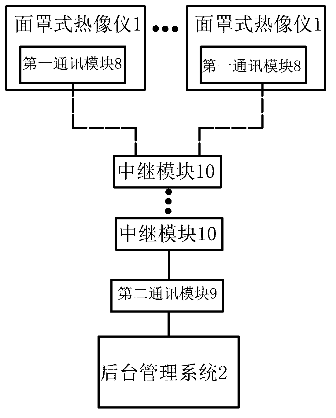
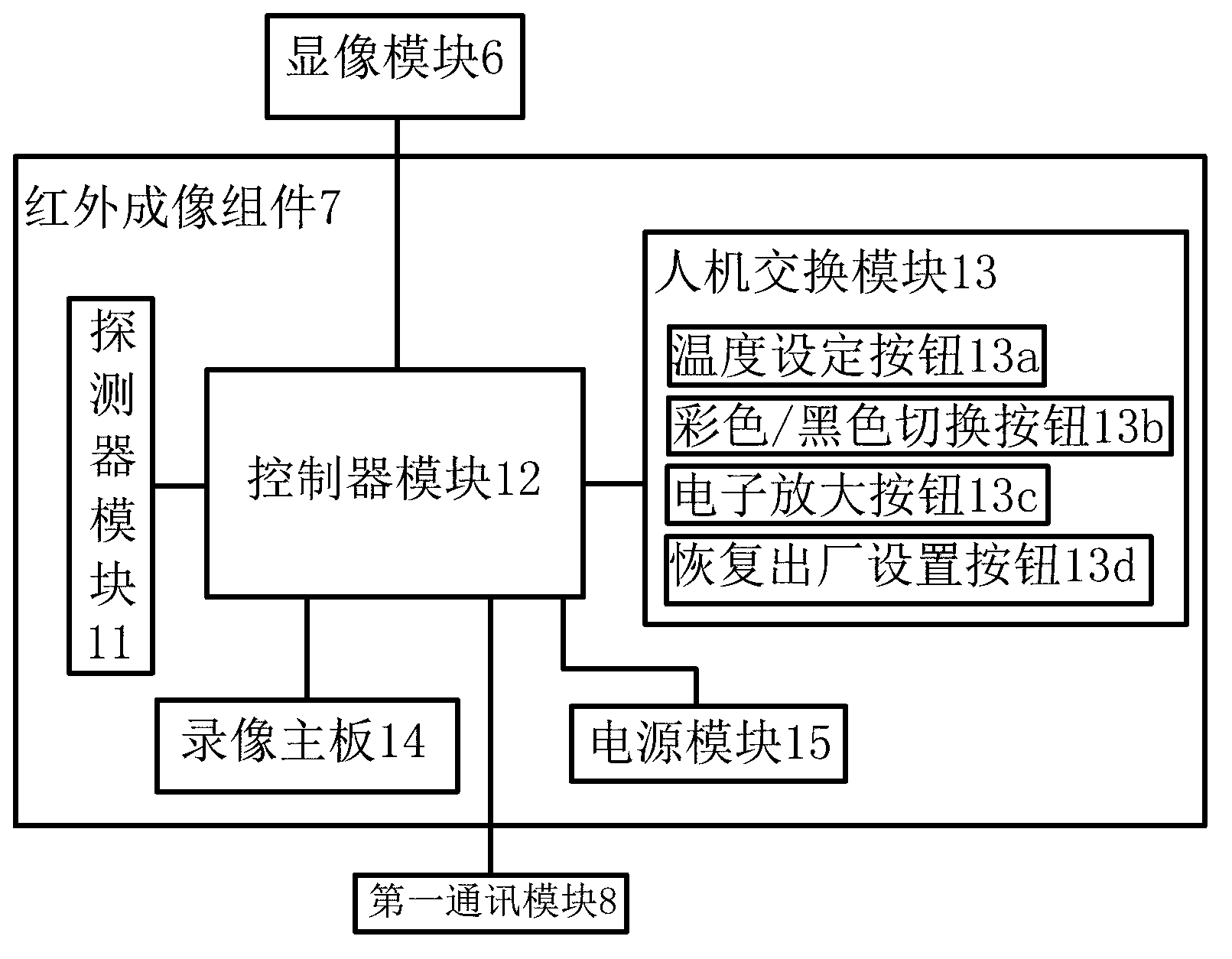
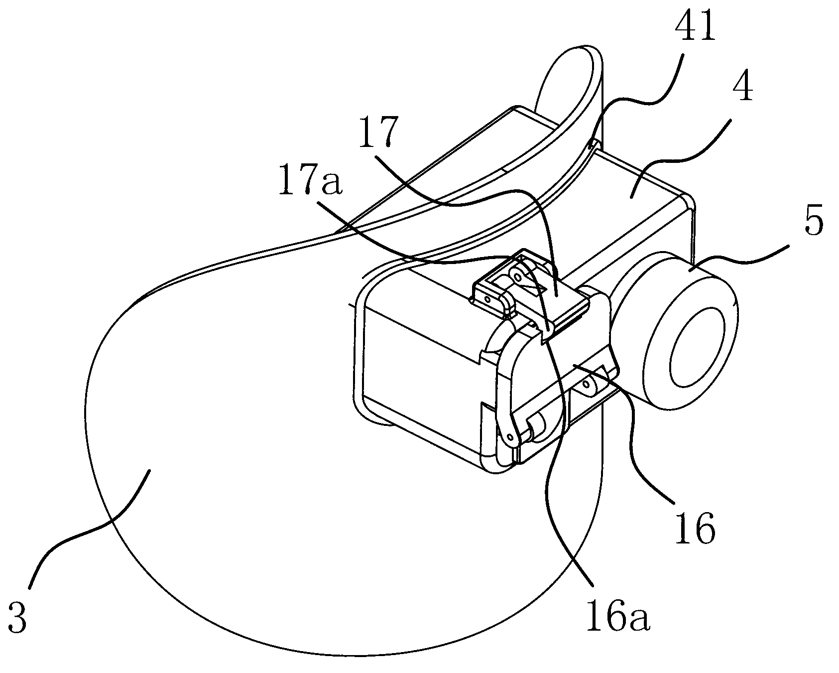
[0021] Such as Figure 1-4 As shown, the thermal mask camera system includes at least one thermal mask camera 1 and a background management system 2 . The mask-type thermal imager 1 includes an arc-shaped mask 3, on which a box body 4 is fixed, and an infrared optical lens 5 is arranged on the end face outside the mask 3 on the box body 4, and the mask 3 is located on the box body 4. A viewfinder 6 is provided on the inner end surface, and an infrared imaging component 7 capable of detecting and displaying images is provided in the box body 5 . The box body 4 is provided with a shutter flap mechanism, and the shutter flap mechanism includes a first plate 16 hinged on the front end of the box body 4 and a second plate 17 hinged on the side of the box body 4. One plate body 16 has a locking groove 16a, and the second plate body 17 has a buckle 17a, and the buckle 17a can be locked in the locking groove 16a.

[0022] The infrared imaging assembly 7 is connected with the infrare...


PUM


Abstract

The invention belongs to the technical field of an optoelectronic device and relates to a mask type thermal imaging system. The mask type thermal imaging system solves the technical problem of unreasonable design and other problems in the prior art. The mask type thermal imaging system comprises at least one mask type thermal imager and a background managing system; the mask type thermal imager comprises an arc mask; a box body is fixed on the mask, the end face at the outer side of the mask on the box body is provided with an infrared optical lens, and the end face at the inner side of the mask on the box body is provided with a view finder; an infrared imaging component is arranged in the box body, the infrared imaging component is connected with the infrared optical lens and the view finder; a first communication module is connected to the infrared imaging component, a second communication module is connected to the background managing system. The mask type thermal imaging system has the advantages of reasonable design, simple structure, low cost, convenient use and operation, large monitoring scale and wide view seeking field; and meanwhile, the mask type thermal imaging system can well protect the infrared optical lens and the detector. Besides, the mask type thermal imaging system can realize the networking and is convenient to deal with various unexpected matters.

Description

technical field [0001] The invention belongs to the technical field of photoelectric equipment, and relates to a thermal imager, in particular to a mask type thermal imager system. Background technique [0002] The thermal imager uses an infrared detector, an optical imaging objective lens and an optical-mechanical scanning system to receive the infrared radiation energy distribution pattern of the measured target and reflect it on the photosensitive element of the infrared detector. Between the optical system and the infrared detector, there is an optical-mechanical The scanning mechanism scans the infrared thermal image of the object to be measured, and focuses on the unit or spectroscopic detector, and the detector converts the infrared radiation energy into an electrical signal, and the amplified, converted or standard video signal passes through the TV screen or monitor Displays an infrared thermal image. Today, with the rapid development of society, fires occur from t...

Claims


Application Information

Patent Timeline
Patent Type & Authority Applications(China)
IPC IPC(8): G01J5/02
Inventor 何宇
Owner 浙江雷邦光电技术有限公司
Why Eureka
Try Eureka