Detachable novel truss node testing device

A test device and detachable technology, applied in the field of detachable new type truss node test device, can solve the problems of insufficient accuracy and reliability, poor economy, complex structure, etc., and achieve improved accuracy and reliability and easy operation. , the clear effect of transmission

Inactive Publication Date: 2012-10-03
TSINGHUA UNIV
View PDF3 Cites 12 Cited by
  • Summary
  • Abstract
  • Description
  • Claims
  • Application Information

AI Technical Summary

Problems solved by technology

[0004] The technical problem to be solved by the present invention is to propose a detachable truss joint test device, which can effectively solve t...

Method used


Image

  • Detachable novel truss node testing device
  • Detachable novel truss node testing device
  • Detachable novel truss node testing device

Examples


Embodiment 1

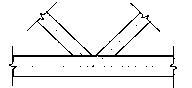
[0034] figure 1 It is a schematic diagram of a test device for testing a K-shaped truss node according to an embodiment of the present invention.

[0035] The structure of the main body 1 of the test device is made according to the Warren truss applied to K-shaped joints, and space for K-shaped joints is reserved in typical positions. At the same time, the strength and stiffness of the bar section of the main body 1 of the test device should be more than 1.5 times that of the truss node 2 to be tested (the truss node 2 to be tested includes the node chord 3 and the node web 5), so as to ensure that the test Finally, the effect of the failure of the truss node 2 to be tested is obtained. The K-shaped truss node 2 to be tested is composed of a node chord 3 and two node webs 5. In order to ensure that the node area of ​​the K-shaped truss node 2 to be tested is not affected by the rod end load, the length of the node chord 3 is taken as 7 to 8 times the outer diameter of the no...

Embodiment 2

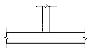
[0039] figure 2 It is a schematic diagram of a test device for testing T-shaped truss nodes according to an embodiment of the present invention.

[0040] The structure of the test device main body 1 is made according to the truss applied to the T-shaped node, and the bar section strength and stiffness of the test device main body 1 are the truss node 2 to be tested (the truss node 2 to be tested includes the node chord 3 and the node 1.5 times of the web member 5) to ensure that the test finally obtains the effect of the failure of the truss node 2 to be tested. The T-shaped truss node 2 to be tested is composed of a node chord 3 and a node web 5, which are perpendicular to each other. The length of the node chord is 7~8 times of the outer diameter of the node chord 3; the length of the node web 5 is 5~6 times of the outer diameter of the node web 5.

[0041]The main body 1 of the test device and the truss node 2 to be tested are connected by three flanges 4 and two flanges...

Embodiment 3

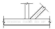
[0044] image 3 It is a schematic diagram of a test device for testing N-shaped truss nodes according to an embodiment of the present invention.

[0045] The structure of the main body 1 of the test device is made according to the truss applied to the N-shaped node, and the cross-sectional strength and stiffness of the bar of the device 1 are the truss node 2 to be tested (the truss node 2 to be tested includes the node chord 3 and the node web 5) more than 1.5 times to ensure that the test finally obtains the effect of the failure of the truss node 2 to be tested. The N-shaped truss node 2 to be tested is composed of a node chord 3 and two node webs 5. In order to ensure that the node area of ​​the N-shaped truss node 2 to be tested is not affected by the rod end load, the length of the node chord 3 is taken as 7 to 8 times the outer diameter; the length of the node web 5 is 5 to 6 times the outer diameter.

[0046] The main body 1 of the test device and the truss node 2 to...


PUM


Abstract

The invention discloses a detachable novel truss node testing device belonging to the field of structural engineering in civil engineering. The detachable novel truss node testing device comprises a main body (1) of the testing device and a truss node (2) to be tested, wherein the main body (1) of the testing device is connected with the truss node (2) to be tested through flanges (4) and flanges (6); a chord member (3) of the node is connected with a main bar (9) of the device by the flanges (4) through bolts; web members (5) of the node are connected with branch bars (10) of the device by the flanges (6) through bolts; a chord member load sensor (7) is distributed at one end part of the chord member (3) of the node; and web member load sensors (8) are distributed at the end parts of the web members (5) of the node. Through applying a simple unidirectional load to the main body (1) of the testing device, multiple boundary conditions can be applied to the truss node (2) to be tested through each connecting bar, so as to simulate the forced state of the truss node (2) to be tested in a real structure. The device can clearly transmit force, is simple and convenient to operate, is economic and reliable, and can be repeatedly utilized.

Description

technical field [0001] The invention belongs to the field of structural engineering in civil engineering, in particular to a detachable novel truss node test device. Background technique [0002] The truss structure has excellent performances such as light weight, high rigidity, good overall performance, beautiful appearance, and convenient fabrication and installation. In recent years, various truss structures have been widely used in engineering practice at home and abroad, such as bridges, exhibition halls, stadiums, dome structures, airport terminals, stations, towering towers, etc. Some large venues such as the National Stadium in Beijing, the National Grand Theater, and the new terminal of the Capital Airport; bridges such as the Zhongxian Yangtze River Bridge in Sichuan and the Zidong Bridge in the South China Sea have adopted truss structures and achieved good engineering results. [0003] The node is the key part of the truss structure, and it is also the area with...

Claims


Application Information

Patent Timeline
IPC IPC(8): G01M99/00
Inventor 韩林海侯超
Owner TSINGHUA UNIV
Why Eureka
Try Eureka