This helps you quickly interpret patents by identifying the three key elements:
Problems solved by technology
Method used
Benefits of technology
Problems solved by technology
Due to the small size of the mobile terminal antenna, it is difficult to achieve ultra-wideband, and its resonant frequency is generally narrow, which can still meet the design requirements in a free space state. The interference of the human body will cause the shift of the resonant frequency of the antenna, reduce the radiation efficiency of the antenna, and cause a serious decline in the performance of the antenna, thus affecting the call or data service
Although there are related technologies at present, most of them are improved by adjusting the matching method between the main channel of the radio frequency signal and the antenna, which brings about a high demand for the output power of the radio frequency power amplifier, thereby additionally increasing the heat of the mobile terminal system. consumption, so far it is not the best solution
Method used
Image
Click on the blue label to locate the original text in one second.
Reading with bidirectional positioning of images and text.
Examples
Embodiment 1
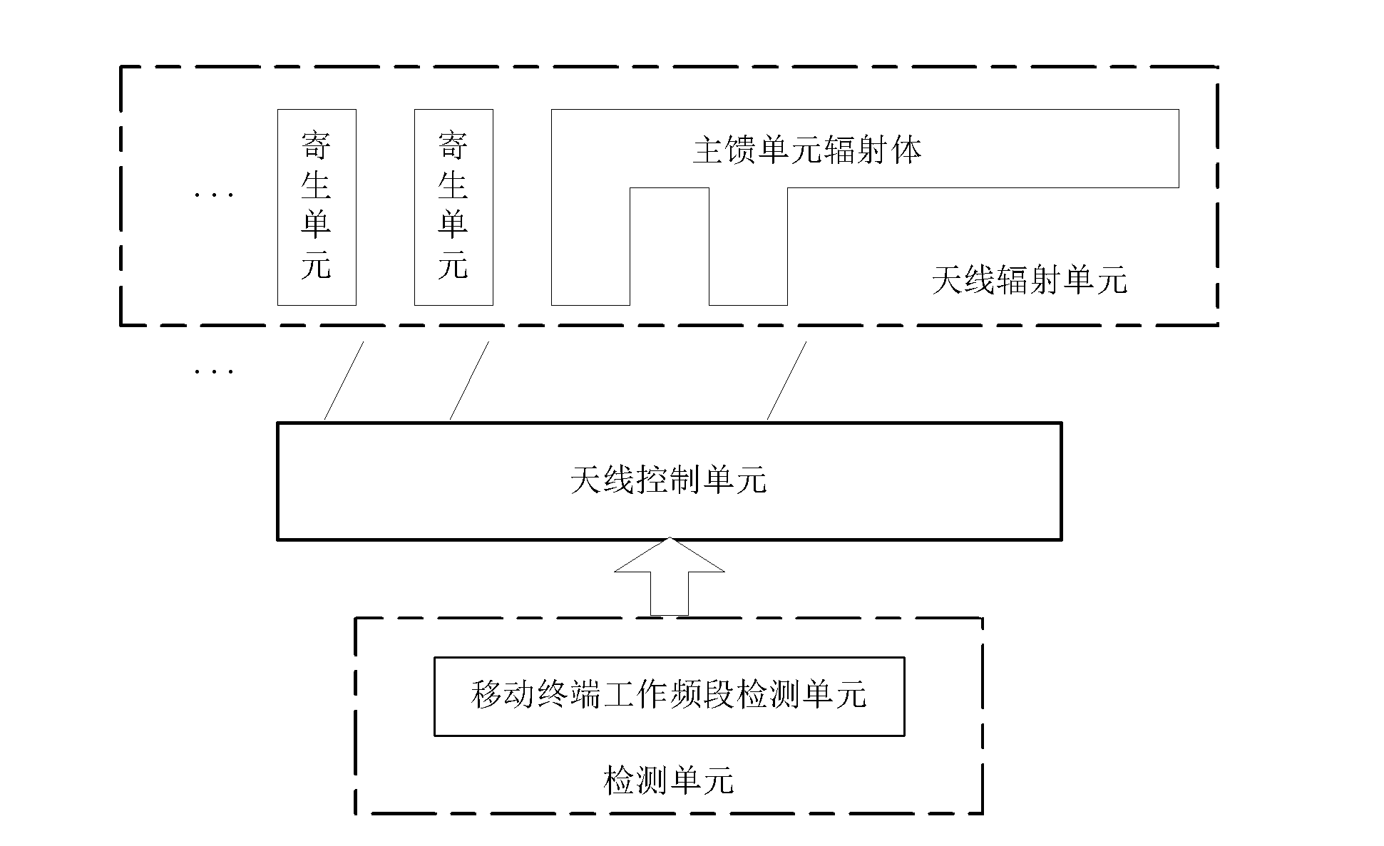
[0043] This embodiment describes a mobile terminal that can optimize the antenna performance of the current frequency band according to the current working frequency band, such as figure 1 As shown, it includes a detection unit, an antenna control unit and an antenna radiation unit. The antenna radiation unit includes a main feed unit radiator and a parasitic unit radiator (including one or more parasitic units), wherein:
[0044] The detection unit is used to detect the current working frequency band of the mobile terminal, and send the detection result to the antenna control unit;
[0045] The antenna control unit is used to receive the detection result sent by the detection unit, and change the impedance characteristic of the radiator of the parasitic unit according to the preset correspondence between the antenna radiation unit and the current working frequency band;
[0046] The radiator of the parasitic unit is used to change the impedance characteristic according to the...
Embodiment 2
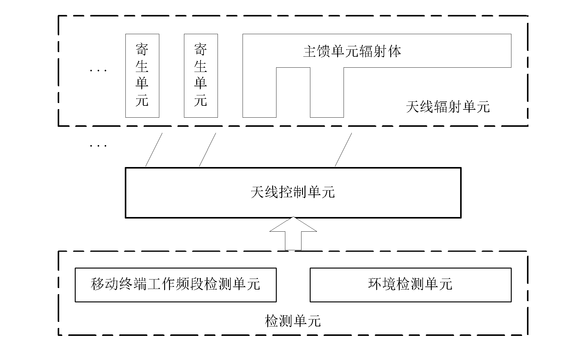
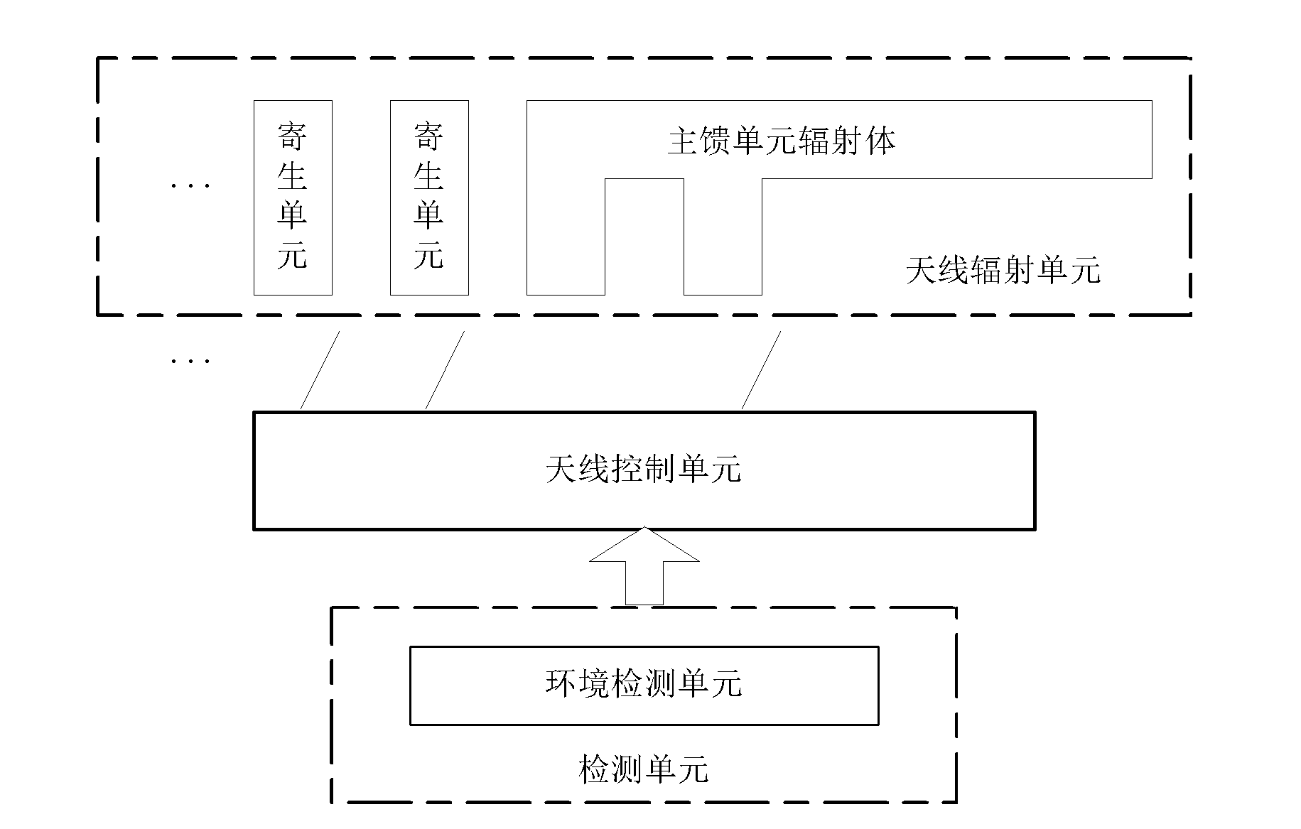
[0055] This embodiment describes a terminal that can improve the performance of the antenna when the human body approaches, such as image 3 As shown, it includes a detection unit, an antenna control unit and an antenna radiation unit. The antenna radiation unit includes a main feed unit radiator and a parasitic unit radiator (including one or more parasitic units), wherein:
[0056] The detection unit is used to detect the current working frequency band of the mobile terminal, and send the detection result to the antenna control unit;
[0057] The antenna control unit is used to receive the detection result sent by the detection unit, and change the impedance characteristic of the radiator of the parasitic unit according to the preset correspondence between the antenna radiation unit and the current working frequency band;
[0058] The radiator of the parasitic unit is used to change the impedance characteristic according to the control of the antenna control unit.
[0059] ...
Embodiment 3
[0066] This example describes the figure 1 The method for the intelligent switch mobile terminal antenna of the shown smart antenna structure, such as Figure 9 shown, including the following steps:
[0067] Step 110, detecting the current working frequency band of the mobile terminal;
[0068] Step 120, according to the preset corresponding relationship between the antenna radiation unit and the current working frequency band, change the impedance characteristics of the parasitic unit radiator (for example, turn on one or more parasitic units in the parasitic unit radiator, and / or turn off the parasitic unit radiator one or more parasitic units in the ).
PUM
Abstract
The invention discloses a method for intelligently switching on / off terminal mobile terminal antenna and a corresponding mobile terminal, to improve the performance of the antenna. The method comprises the steps of detecting the current working frequency range and ambient environment of the terminal; and changing impedance characteristics of a radiating body of a parasitic element according to the pre-set corresponding relations of an antenna radiating unit, environment conditions and the current working frequency range. Another method comprises the following steps of detecting the current working frequency range of the terminal; and changing the impedance characteristics of the radiating body of the parasitic element according to the pre-set corresponding relations of the antenna radiating unit and the current working frequency range. Another method comprises the steps of detecting the current ambient environment of the terminal and changing the impedance characteristics of the radiating body of the parasitic element according to the pre-set corresponding relations of the antenna radiating unit and the environment conditions. The terminal comprises a detection unit, an antenna control unit and the antenna radiating unit. As the method and the terminal are adopted, the antenna radiating unit is controlled by the working frequency range of the terminal and / or the environment conditions, and further the communication quality of a wireless communication system air interface is improved.
Description
technical field [0001] The invention relates to the technical field of mobile communication, in particular to a method for intelligently switching the antenna of a mobile terminal and a corresponding mobile terminal. Background technique [0002] With the advent of the 3G era, mobile communication has fully entered the 3G era, and the development of mobile communication has also entered a more humane and intelligent era. Especially with the rapid development of sensor networks, people's requirements for mobile communications are not limited to simple voice call functions. Humanized and intelligent mobile terminals with multi-network integration are the most basic requirements for mobile terminals in the new era. need. [0003] At the same time, with the popularization of multi-mode smart mobile terminals, especially with the rapid development of LTE technology, the antenna design requirements for multi-mode mobile terminals including 2G, 3G and 4G technologies in the future...
Claims
Application Information
Patent Timeline
Application Date:The date an application was filed.
Publication Date:The date a patent or application was officially published.
First Publication Date:The earliest publication date of a patent with the same application number.
Issue Date:Publication date of the patent grant document.
PCT Entry Date:The Entry date of PCT National Phase.
Estimated Expiry Date:The statutory expiry date of a patent right according to the Patent Law, and it is the longest term of protection that the patent right can achieve without the termination of the patent right due to other reasons(Term extension factor has been taken into account ).
Invalid Date:Actual expiry date is based on effective date or publication date of legal transaction data of invalid patent.

