Retractable shank for machine tools and use of said retractable shank in machine tools

一种伸缩式、柄杆的技术,应用在金属加工机械零件、大型固定成员、夹固等方向,能够解决铣削主轴箱长、失去工作区域等问题

Active Publication Date: 2012-10-03
SORALUCE S COOP
View PDF5 Cites 2 Cited by
  • Summary
  • Abstract
  • Description
  • Claims
  • Application Information

AI Technical Summary

Problems solved by technology

[0006] The disadvantage of this solution is that the milling headstock is too long when placed on the tool box or carriage, i.e. the tool mounted in the headstock is far from the column of the machine, thus losing the working area

Method used


Image

  • Retractable shank for machine tools and use of said retractable shank in machine tools
  • Retractable shank for machine tools and use of said retractable shank in machine tools
  • Retractable shank for machine tools and use of said retractable shank in machine tools

Examples


Embodiment Construction

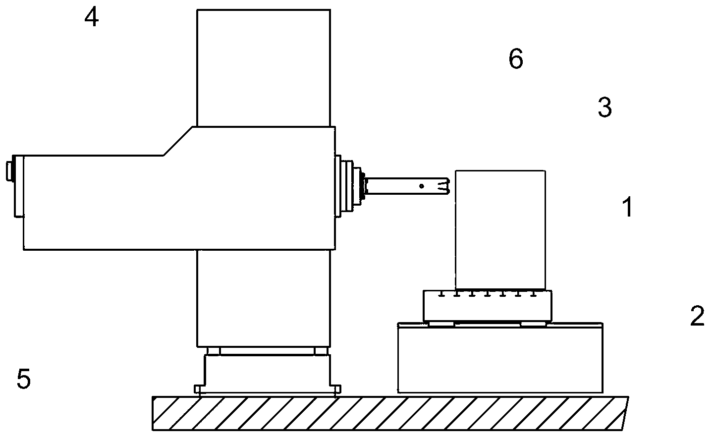
[0024] The object of the invention relates to a telescopic shank for machine tools such as milling and boring machines, in which the unit formed by the rotating bushing and the stationary bushing is divided, there is at least one front unit, which is easily accessible by extracting outwards or towards It is removed by moving inwards, by which it defines a space in the tool box allowing different headstocks to be assembled.

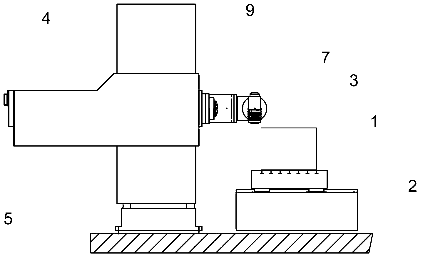
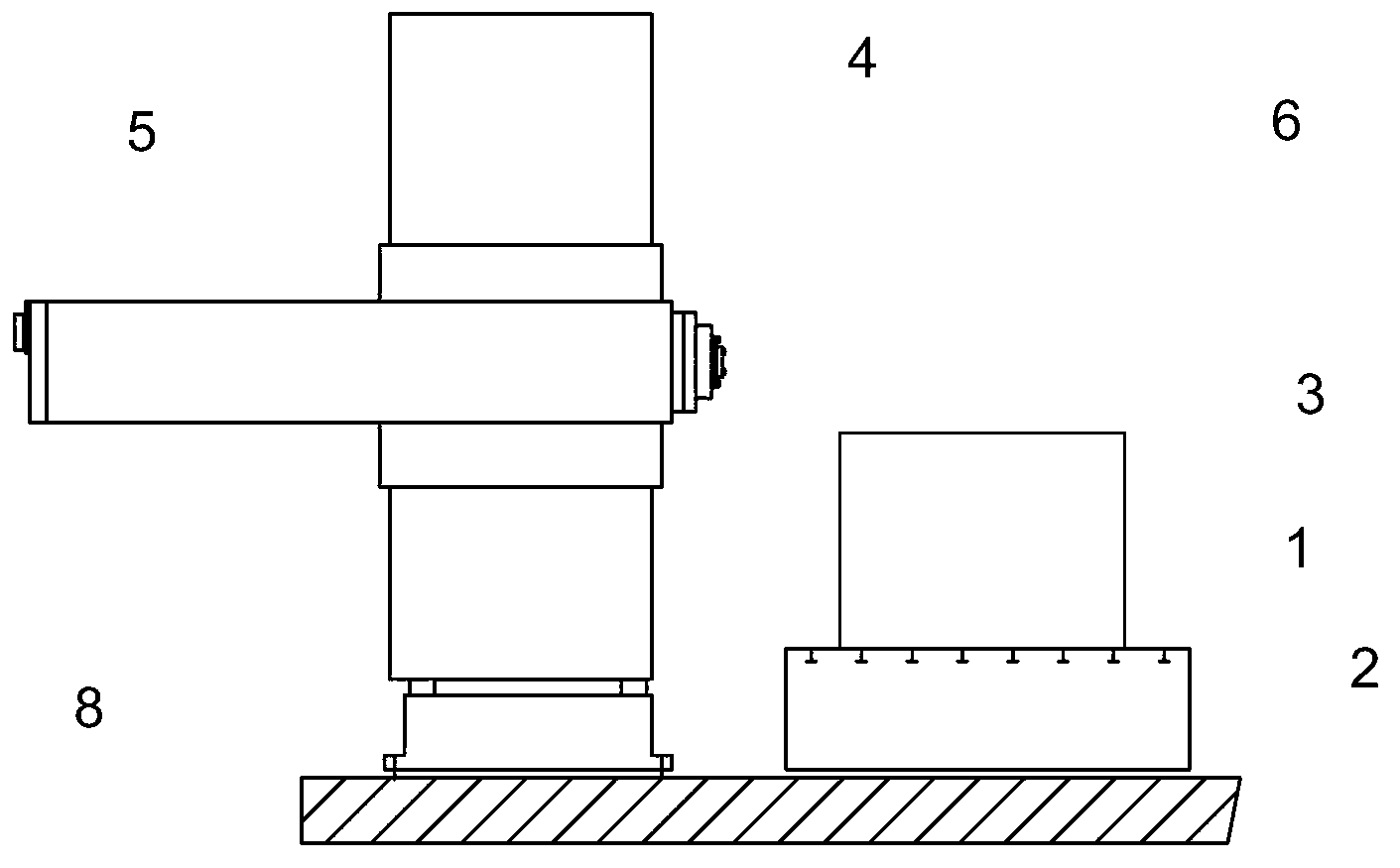
[0025] available at Figure 1A to Figure 1D See the different types of machine tools in, Figure 1A The machine shown has: a horizontal platform (1) fixed to the ground (2) on which the parts to be machined (3) are placed; columns (4), carriages (5) or consoles on which slide vertically , inside the bracket or console there is a handle (6) which slides horizontally in a direction perpendicular to the longitudinal axis of said table (1). Figure 1B show with Figure 1A A similar machine tool where the shank (6) is retracted to facilitate engagement with t...


PUM


Abstract

The invention relates to a retractable shank for machine tools and to the use of said retractable shank in machine tools made up of a shank core (13), on which is arranged at least one front unit made up of a rotating bush (17) connected, via a set of bearings (16), relative to a stationary portion of the structure of the machine, said front unit being removable by extraction towards the outside or by moving towards the inside, leaving a space (19) which can house the rear rotary shaft of the headstock.

Description

technical field [0001] The invention concerns a replacement of the headstock in machine tools such as milling and boring machines, for which purpose a telescopic handle is proposed which allows the assembly of different headstocks, the rear shaft of which is inside the machine tool. Background technique [0002] In the field of machine tools there are different types of machines, such as milling machines and boring machines, which are formed by: a horizontal platform fixed to the ground, on which the part to be machined is set; a column, carriage or console slides vertically on it, Inside this bracket or console is provided a tool box and / or handle which slides horizontally in a direction perpendicular to the longitudinal axis of the table. [0003] These machines have different types of configurations according to the movement of their different structural parts; therefore, the table on which the parts to be machined are placed can be fixed to the ground, while the column t...

Claims


Application Information

Patent Timeline
Patent Type & Authority Applications(China)
IPC IPC(8): B23Q1/70
CPCB23Q5/043B23Q1/70B23Q5/225Y10T409/309296Y10T409/309352B23Q3/12
Inventor A·M·门迪亚奥拉瓦里亚
Owner SORALUCE S COOP
Why Eureka
Try Eureka