Tracking and monitoring camera device and remote monitoring system using same

A technology of camera device and camera unit, which is applied in the direction of closed-circuit television system, parts of TV system, parts of color TV, etc. It can solve the problems of grasping the continuous action line of the action object, increasing the size of the device, and increasing the constraints, etc. Achieve perfect monitoring function, low manufacturing cost, and ensure the effect of vision

Inactive Publication Date: 2012-10-03
YOUNG KOOK ELECTRONICS
View PDF6 Cites 12 Cited by
  • Summary
  • Abstract
  • Description
  • Claims
  • Application Information

AI Technical Summary

Problems solved by technology

[0010] However, in the device described in the above-mentioned document, since a plurality of combination cameras and PTZ cameras are separately manufactured and installed on the support rod, not only the size of the device becomes larger, but also the installation space or installation method is affected. The constraints also increase the problem
At the same time, in this system, multiple combined cameras only play the role of sensors. In fact, it is impossible to grasp the continuous action line of the moving object from the images obtained through the combined cameras.

Method used


Image

  • Tracking and monitoring camera device and remote monitoring system using same
  • Tracking and monitoring camera device and remote monitoring system using same
  • Tracking and monitoring camera device and remote monitoring system using same

Examples


Embodiment Construction

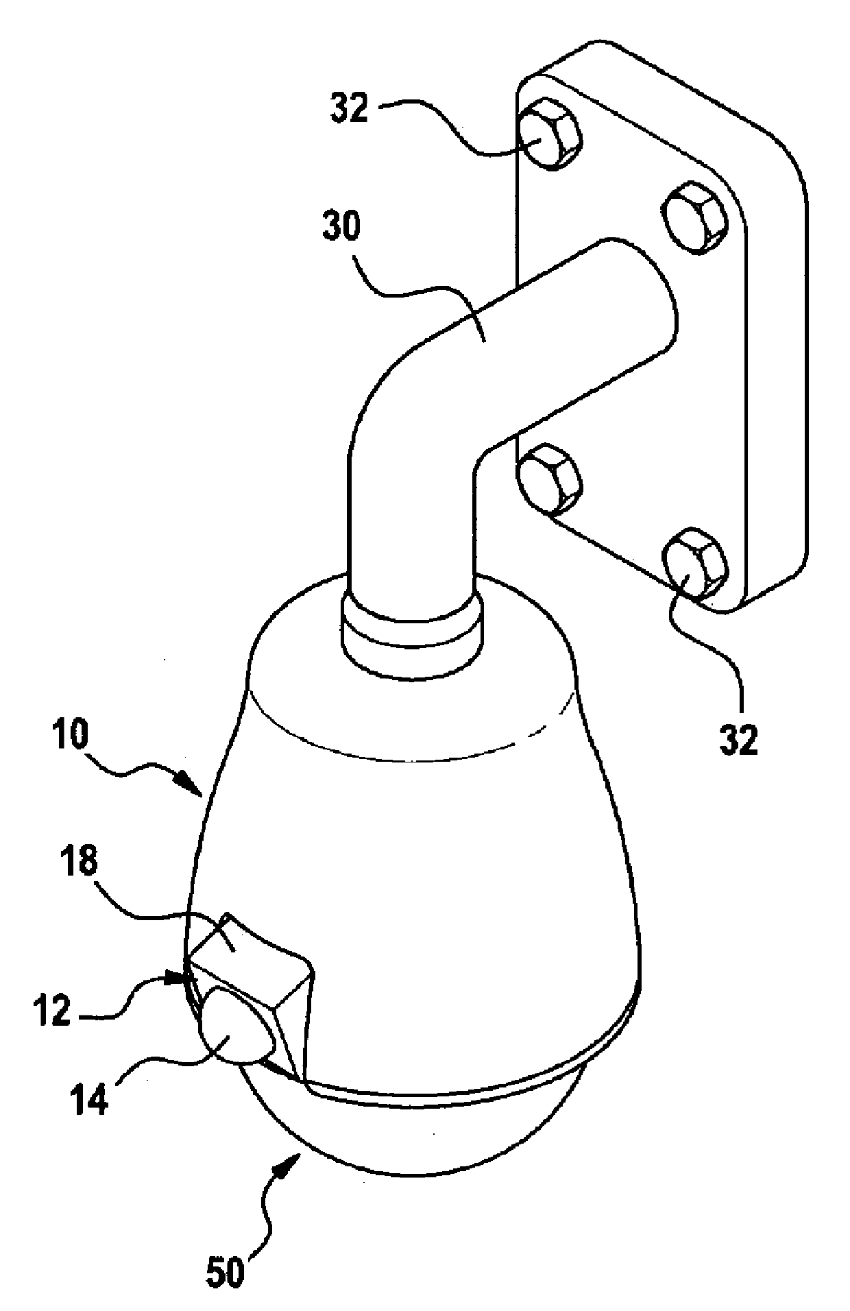
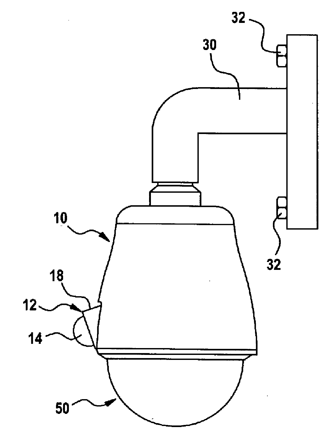
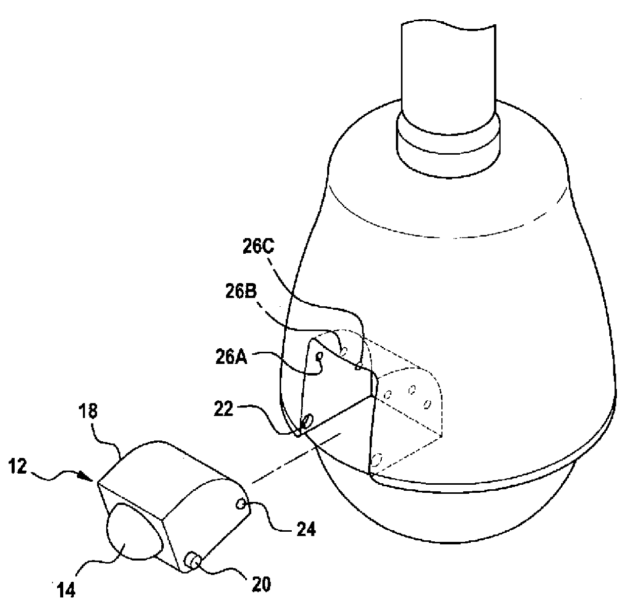
[0047] refer to figure 1 and figure 2 The imaging device according to the preferred embodiment of the present invention has a main frame 10 substantially in the form of a bell and a dome 50 provided below the main frame 10 . Preferably, the shell of the main frame 10 is formed of metal or opaque synthetic resin material, and the dome 50 is formed of translucent synthetic resin material. A first camera unit 12 is provided on the lower side of the housing of the main frame 10 via the support protrusion 18 . In the dome 50, a second camera unit ( figure 1 not shown). A bracket 30 for installing the camera device on the wall can be provided on the upper end of the main frame 10 .

[0048] The supporting protrusion 18 is made of synthetic resin material, supports the first camera unit 12 spatially, and determines the direction of the first camera unit 12 . In a preferred embodiment, the supporting protrusion 18 is disposed on the lower side of the outer peripheral surface of ...


PUM


Abstract

A camera device can smoothly perform an operation for monitoring an entire situation over a wide area and an intensive monitoring and tracking operation for a specific area or a specific object by integrating a wide monitoring camera and an intensive monitoring camera, and a shadow area is not generated in an area directly below. The camera device of the present invention includes a main frame, a first camera unit, and a second camera unit. The main frame includes a lens location surface of which a normal is directed to a lower part of the outside. The first camera unit comprises: a wide-angle lens which is provided at the main frame and is arranged on the lens location surface to direct an optical axis thereof to the lower part of the outside; and a first image sensor for converting incident light received through the wide-angle lens to an electric signal, so as to photograph circumferential images including a point directly underneath the monitoring camera device. The second camera unit comprises a second image sensor and is provided to rotate horizontally and vertically to the main frame. Desirably, the main frame is protruded from an outer surface to the outside and includes a supporting protrusion having a front surface facing the outside in the downward direction and the wide-angle lens can be attached to the front surface of the supporting protrusion.

Description

technical field [0001] The present invention relates to a television imaging device, and more specifically, to a composite monitoring imaging device having a plurality of cameras. Meanwhile, the present invention relates to a remote monitoring system using such a camera device. Background technique [0002] A security / surveillance system using a camera for surveillance is widely used for access control or theft prevention. Not only banks, military facilities, and other public facilities or commercial buildings with security needs, but also general roads or residences will also be equipped with such security / surveillance systems, and this trend is growing. [0003] Although a variety of surveillance camera devices are used, one of the most widely used camera devices for the execution of this application is the cloud that can be rotated horizontally (i.e., panning) and vertically (i.e., tilting) and can be zoomed in / out It is a fast dome camera device with omni-directional ...

Claims


Application Information

Patent Timeline
Patent Type & Authority Applications(China)
IPC IPC(8): H04N7/18H04N5/225G03B19/00G03B30/00
CPCH04N5/23238G08B13/1963G08B13/19643G08B13/19626H04N5/247G08B13/19632H04N7/181H04N23/698H04N23/90
Inventor 金培熏李智焕
Owner YOUNG KOOK ELECTRONICS
Why Eureka
Try Eureka