
Vibrating platform with precise driving mechanism

A driving mechanism and vibration platform technology, which is applied in the testing of machines/structural components, vibration testing, measuring devices, etc., can solve the problems of difficult realization of micro-nano level vibration equipment, and achieve good rigidity, precise and controllable vibration displacement, good reliability

Active Publication Date: 2012-10-10
SHANGHAI JIAO TONG UNIV
View PDF6 Cites 34 Cited by
  • Summary
  • Abstract
  • Description
  • Claims
  • Application Information

AI Technical Summary

Problems solved by technology

Therefore, it is difficult to achieve micro-nano level vibration equipment based on traditional vibration equipment.

Method used


Image

  • Vibrating platform with precise driving mechanism
  • Vibrating platform with precise driving mechanism
  • Vibrating platform with precise driving mechanism

Examples


Embodiment 2

[0054] Such as Figure 6 As shown, the drive mechanism 2 is: the driver 4, the frame body and the enlarged displacement output end rod 7 connected thereto and the displacement output rod of the driver 4, wherein: the displacement output rod of the driver 4 is horizontally arranged on the elliptical structure In the frame type body and the driver 4 is located in the middle of the driver 4 displacement output rod, and the enlarged displacement output end rod 7 is arranged on the top of the frame type body of the oval structure.

[0055] The position where the displacement output rod of the driver 4 is in contact with the frame body is provided with snap rings;

[0056] Linear bearings are provided at the position where the amplified displacement output rod 7 and the displacement output rod of the driver 4 are in contact with the support frame.

[0057] The drive mechanism 2 can act to form as Figure 7 The shaker setup shown. The displacement produced by it to the displacemen...

Embodiment 3

[0059] Such as Figure 7-Figure 9 As shown, this embodiment includes: a support frame 1 , one or three driving mechanisms 2 arranged in the support frame 1 and a vibrating platform 3 connected thereto.

[0060] The drive mechanism 2 is composed of a driver 4 and a driver output rod 5 fixedly connected thereto. The top end of the driver output rod 5 is hinged to the drive platform 4 .

[0061] Described hinge all adopts spherical hinge or cross hinge 19 to realize.

[0062] When working, the three-degree-of-freedom movement realized is: three vibration platforms with precision drive mechanisms at the three fulcrums move up and down the vibration platform 4 simultaneously; and one of the fulcrums does not move, and the other two move simultaneously. Swing form with a small angle; thereby realizing a reciprocating linear motion and two swinging motions, such a three-degree-of-freedom motion platform.


PUM


Abstract

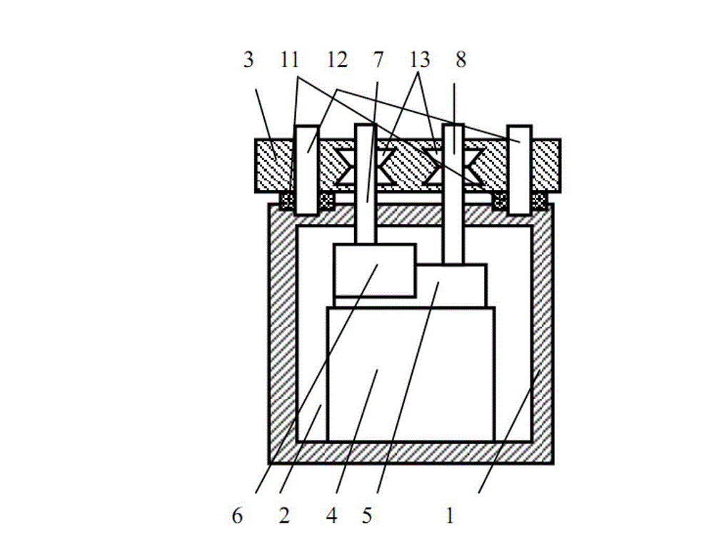
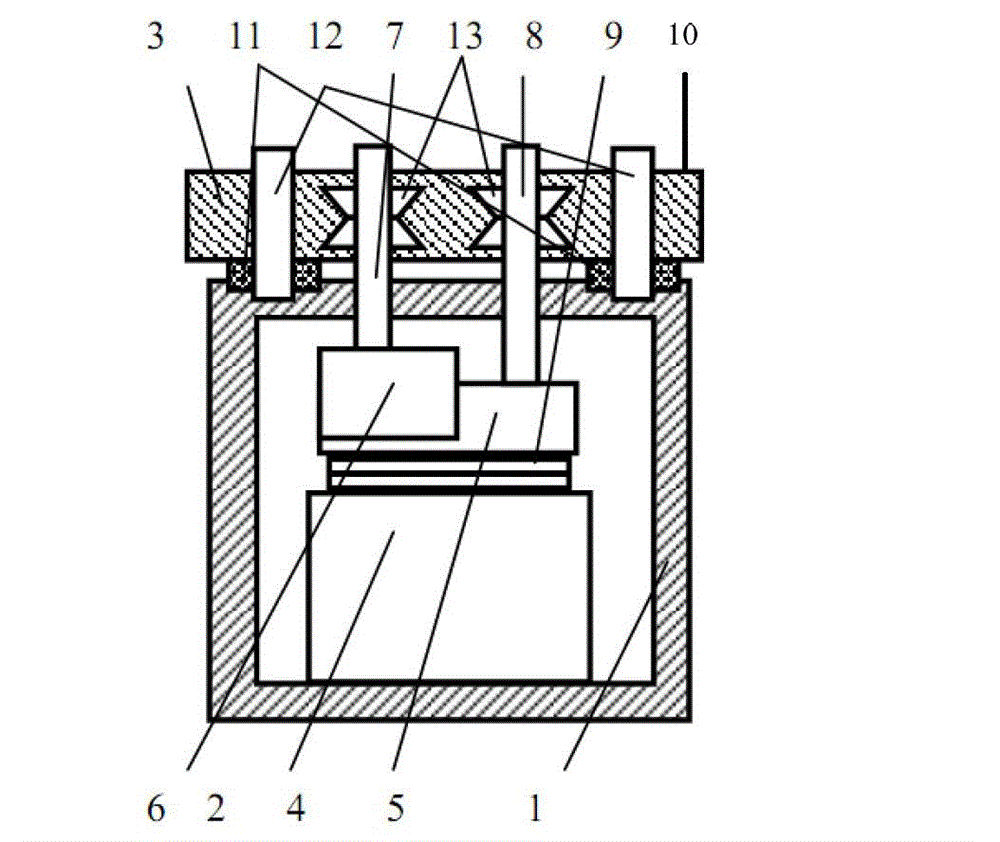
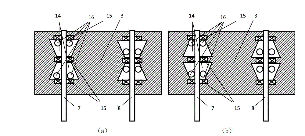
A vibrating platform with a precise driving mechanism in the technical field of precise driving comprises a support frame, at least one driving mechanism arranged in the support frame and a vibrating platform body connected with the driving mechanism. The driving mechanism comprises a driver, a driver outputting rod, a drive displacement amplifying mechanism, an amplifying displacement output end rod and a direct displacement output end rod, wherein the driver, the driver outputting rod and the drive displacement amplifying mechanism are sequentially arranged from bottom to top, and the amplifying displacement output end rod and the direct displacement output end rod are respectively arranged on the drive displacement amplifying mechanism and the driver outputting rod. The vibrating platform with the precise driving mechanism produces direct displacement driving vibration based on flexible deformation of an intelligent material, is simple in structure, high in reliability and drive efficiency, accurate and controllable in amplitude and capable of achieving wide amplitude particularly from nanometer to a plurality of millimeters and achieving a wideband from a quasi-static state to high frequency, and has heavy-load vibrating capability.

Description

[0001] This application is a divisional application with the application number 201110039211.2, the application date is 2011.2.17, and the invention name is "Precision Drive Vibration Table". technical field [0002] The invention relates to a device in the field of precision drive technology, in particular to a vibration platform with a precision drive mechanism. Background technique [0003] In recent years, due to the development of technology in the field of micro-nano devices and ultra-precision manufacturing, there is an urgent need for an active control vibration platform for micro-nano and disturbed vibrations to solve the problem of micro-vibration in the process of micro-nano devices and ultra-precision processing. At present, vibration equipment is mainly realized by hydraulic, pneumatic, electromagnetic and mechanical vibration methods. Since these vibration devices are realized by hydraulic, pneumatic and mechanical vibration behaviors, there are many components...

Claims


Application Information

Patent Timeline
Patent Type & Authority Applications(China)
IPC IPC(8): G01M7/02G01M7/06
Inventor 杨斌堂
Owner SHANGHAI JIAO TONG UNIV
Learn More