
Mold locking structure for injection mold

A technology of clamping and clamping, which is applied in the field of mold manufacturing, can solve the problems of inability to seal glue, front mold slider rubbing, product burrs, etc., and achieves the effect of simple structure and avoiding rubbing damage.

Active Publication Date: 2015-01-28
ZHONGSHAN JINCHENG PLASTIC PROD CO LTD
View PDF2 Cites 0 Cited by
  • Summary
  • Abstract
  • Description
  • Claims
  • Application Information

AI Technical Summary

Problems solved by technology

[0005] But above-mentioned clamping structure of injection mold has the following defects: 1. The clamping structure adopts nylon shutter, which is easy to wear
2. It is impossible to realize the dynamic template and the static template to close the mold first
3. For injection molds with front mold sliders, the final closing of the dynamic and static templates will cause the front mold sliders to rub and burn, unable to seal the glue, and the product will have burrs

Method used


Image

  • Mold locking structure for injection mold
  • Mold locking structure for injection mold
  • Mold locking structure for injection mold

Examples


Embodiment Construction

[0025] Embodiments of the present invention will be described in detail below in conjunction with the accompanying drawings.

[0026] like Figure 4 to Figure 9 As shown, an injection mold clamping structure includes a static mold part 100, a movable mold part 200 and a mold clamping assembly 400. The static mold part 100 includes a panel 101, a nozzle plate 102, a static template 103, and a nozzle plate from front to back. A compression spring 104 is arranged between 102 and the static template 103, and the movable mold part 200 includes a movable template 201 and its driving device (not shown in the figure); wherein, a pull rod penetrating through the nozzle plate is fixed on the nozzle plate 102 300, the upper end of the pull rod is provided with a first limit end 301, and the lower end of the pull rod is provided with a second limit end 302; the panel 101, the static template 103 and the movable template 201 are provided with guides corresponding to the pull rod Channels ...


PUM


Abstract

The invention relates to a mold locking structure for an injection mold. The mold locking structure comprises a movable mold part, a static mold part and a mold locking assembly, wherein the static mold part is composed of a face plate, a top clamp plate and a static template, a compression spring is provided between the top clamp plate and the static template, the movable mold comprises a movable template and a drive unit, a pull bar penetrating the top clamp plate is fixedly arranged on the top clamp plate, the upper end of the pull bar is provided with a first limit end, the lower end of the pull bar is provided with a second limit end, the face plate, the static template and the movable template are provided with guide channels corresponding with the pull bar, the upper end of the pull bar extends into the guide channel of the face plate and is capable of sliding up and down along the guide channel, a stopping part matching with the first limit end of the pull bar is provided in the guide channel of the face plate, the lower end of the pull bar extends into the guide channels on the static template and the movable template and is capable of sliding up and down along the guide channels, a stopping part matching with the second limit end of the pull bar is provided in the guide channel of the static plate, and the mold locking assembly comprises a mold locking buckle body, a push rod and a first locking block. The mold locking structure provided in the invention is simple and reliable.

Description

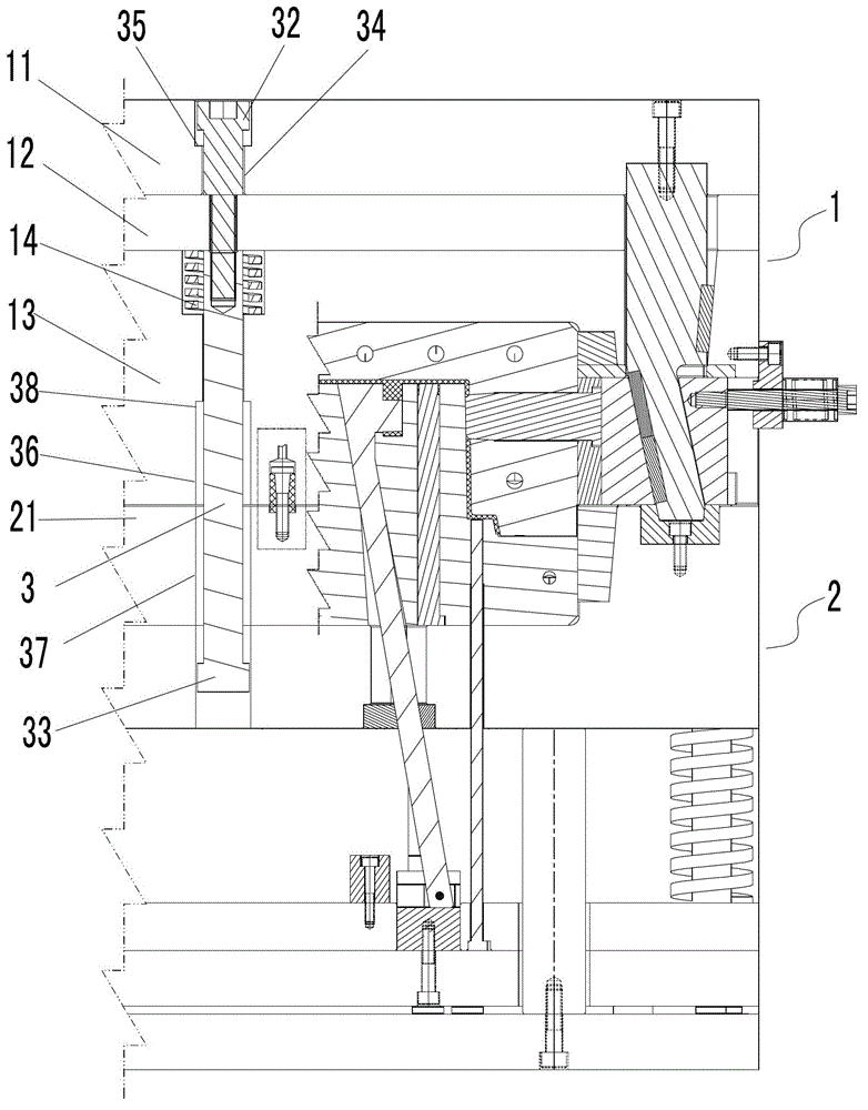
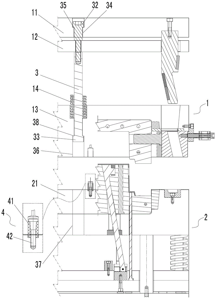
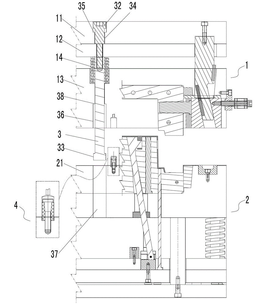
Technical field: [0001] The invention belongs to the field of mold manufacturing, in particular to a clamping structure of an injection mold. Background technique: [0002] like figure 1 To such as image 3 As shown, an existing injection mold includes a static mold part 1, a movable mold part 2 and a mold clamping assembly 4. The static mold part includes a panel 11, a nozzle plate 12, a static template 13, and a nozzle plate 12 from front to back. A compression spring 14 is provided between the static template 13, and the movable mold part includes a movable template 21 and its driving device 22, wherein, the nozzle plate 12 is fixedly provided with a pull rod 3 that runs through the nozzle plate, and the upper end of the pull rod is provided with a second A limit end 32, the lower end of the pull rod is provided with a second limit end 33, the panel 11, the static template 13 and the movable template 21 are provided with a guide channel corresponding to the pull rod 31,...

Claims


Application Information

Patent Timeline
Patent Type & Authority Patents(China)
IPC IPC(8): B29C45/66
Inventor 李雪军欧永波
Owner ZHONGSHAN JINCHENG PLASTIC PROD CO LTD
Learn More