
Illumination device

A technology for lighting devices and sensing devices, which is applied to lighting devices, fixed lighting devices, components of lighting devices, etc., and can solve problems such as imaging errors

Active Publication Date: 2012-10-17
海拉有限双合股份公司
View PDF8 Cites 8 Cited by
  • Summary
  • Abstract
  • Description
  • Claims
  • Application Information

AI Technical Summary

Problems solved by technology

Due to the relatively wide extent of the optical unit designed as a lens, however, imaging errors occur in the peripheral regions of the light distribution, which limits the deglare in these peripheral regions.

Method used


Image

  • Illumination device
  • Illumination device
  • Illumination device

Examples


Embodiment Construction

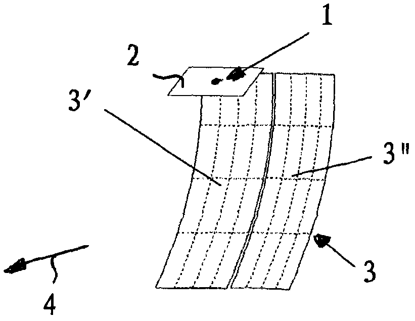
[0021] The lighting device according to the invention is used as a headlight in motor vehicles for the realization of a glare-free high beam function. Such headlights are supposed to be able to implement a dynamic light function (Advanced Front Lighting System AFS), which enables traffic-dependent illumination of the motorway or traffic area. For this purpose, the LED light sources 1 of the headlights are switched on or off or dimmed (changed in brightness) by means of a control device, not shown. The control device is connected on the input side to a sensor device which is designed to detect oncoming and / or preceding road users (objects). According to the sensing data provided by the sensing device, the LED light source 1 of the lighting device is controlled by the control device, that is, turned on or off or dimmed.

[0022] In the present exemplary embodiment, the LED light sources 1 configured as LED chips are combined into an LED lighting field 2 (LED array), so that a r...


PUM


Abstract

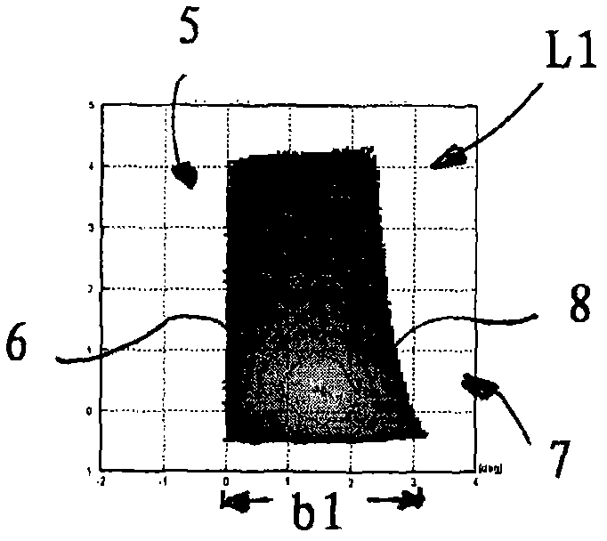
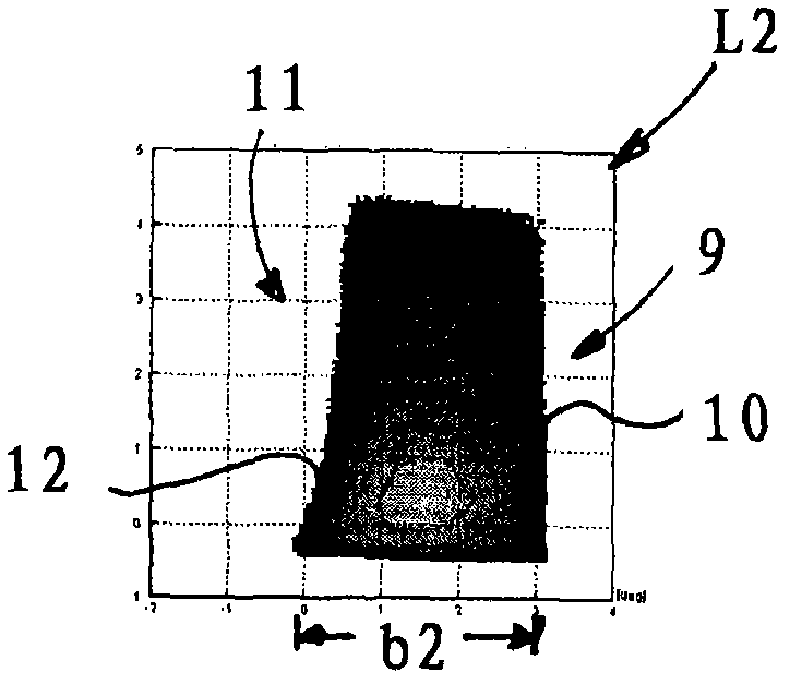
Illumination device for a dazzle-free high beam function with a plurality of LED light sources and an optical unit, with a sensor appliance to detect approaching road users and / or road users travelling in front, with a control mechanism which activates the LED light sources by means of dimming or turning them on and off depending on the sensor data supplied by the sensor assembly in such a way that an anti-dazzling area of the high beam function corresponding to the approaching road user and / or the road user travelling in front is created to prevent the road user from being dazzled, wherein at least the optical unit assigned to the high beam function includes optical elements assigned to the same LED light source, thereby producing least two light spots for every LED light source. On a test screen a first light spot comprises a vertical light / dark boundary on a left side and a second light spot comprises a vertical light / dark boundary on a right side, and that the optical elements are designed in such a way that the first light spot and the second light spot can be superimposed on each other to create a combined light spot, wherein the combined light spot comprises the vertical light / dark boundary of the first light spot or the second light spot, respectively on the left side and the right side.

Description

technical field [0001] The invention relates to a lighting device for realizing a high beam function without glare, which has: an optical unit for generating a high beam function and a plurality of LED light sources; a sensor device for detecting oncoming and / or A road participant driving ahead; a control device, which controls the LED light source by dimming or by switching on and off on the basis of the sensor data provided by the sensor device, so that in the high beam function it is formed in relation to the oncoming and and / or corresponding deglare areas for road users driving in front for the deglare of the road users. Background technique [0002] A lighting device with an LED light source and an optical unit associated therewith is known from DE 10 2009 000 557 A1. The optical unit is designed as a reflector having two reflector sections that are oriented differently relative to the LED light source. The first reflector section images the LED light source as a firs...

Claims


Application Information

Patent Timeline
Patent Type & Authority Applications(China)
IPC IPC(8): F21V7/10F21V23/04F21Y101/02
CPCF21S48/115F21V7/10F21S8/12B60Q2300/054F21S48/1159F21S48/1747B60Q1/085B60Q1/143B60Q1/08B60Q2300/45F21S48/1335F21V7/00F21V23/04F21S41/323F21S41/663F21S41/148
Inventor D·克利比施
Owner 海拉有限双合股份公司
Learn More