Self-operated discharging valve

An unloading valve, self-operated technology, applied in the field of unloading valves, can solve the problems of complex driving device system, energy consumption, high cost, etc.

Inactive Publication Date: 2012-10-24
江苏东源阀门检测技术有限公司
View PDF3 Cites 3 Cited by
  • Summary
  • Abstract
  • Description
  • Claims
  • Application Information

AI Technical Summary

Problems solved by technology

[0003] In order to overcome the disadvantages of the existing unloading valve that adopts a driving device system that is complex, high in cost,

Method used


Image

  • Self-operated discharging valve

Examples


Example Embodiment

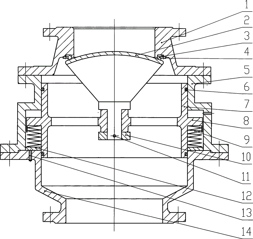
[0010] Such as figure 1 As shown, a self-operated discharge valve includes a valve cover 1, a middle valve body 5, a valve disc 2, a sealing ring 3, a pressing ring 4, and a lower valve body 14. The sealing ring 3 is fixed on the valve cover 1 through the pressing ring 4 Inside, it forms a sealing pair with the valve disc 2. The valve cover 1 and the middle valve body 5, the middle valve body 5 and the lower valve body 14 are connected by fasteners. There is a piston 7 in the middle valve body 5, and the valve disc 2 rod The part extends into the piston 7, and is fixed on the piston 7 by the fixing plate 10 and the connecting pin 11. The piston 7 is sealed with the middle valve body 5 and the lower valve body 14 by the O-ring 6. There is also a boss 8 on the piston 7 A spring 9 is installed between the lower part of the table 8 and the end surface of the lower valve body 14. The lower part of the spring 9 is also equipped with an adjusting ring 12, and the end surface of the l...


PUM


Abstract

The invention provides a self-operated discharging valve which comprises a valve cover, a middle valve body, a valve clack, a sealing ring, a pressing ring and a lower valve body, wherein the sealing ring is fixed in the valve cover through the pressing ring to form a sealing pair with the valve clack, the valve cover is connected with the middle valve body through a fastening member, the middle valve body is connected with the lower valve body through a fastening member, a piston is further arranged in the middle valve body, and a rod portion of the valve clack extends into the piston and is fixed on the piston through a fixing plate and a connection pin. The piston is connected with the middle valve body and the lower valve body through an O-shaped sealing ring, a boss is further arranged on the piston, a spring is further installed between the lower portion of the boss and the end face of the lower valve body, an adjusting ring is further arranged on the lower portion of the spring, a plurality of thread holes are arranged on the end face of the lower valve body under the adjusting ring, and adjusting screws are arranged in the thread holes. The self-operated discharging valve has the advantages of being capable of being opened by self weight of media without any external power and being capable of achieving on-line stepless regulation.

Description

technical field [0001] The invention relates to a valve device, in particular to a discharge valve used in the metallurgical industry. Background technique [0002] At present, the unloading valves used in the ash unloading system in the metallurgical industry generally adopt the form of ball valves or bell valves. The common feature is that the valve is operated by a driving device. First, the system is complex, the cost is high, and it consumes energy. There are also domestic methods that use materials. Gravity is used to realize self-unloading, but it cannot be adjusted. Contents of the invention [0003] In order to overcome the disadvantages of the existing unloading valve using a driving device that is complex, costly, and consumes energy, and cannot be adjusted when using a self-operated unloading valve, the present invention provides a self-operated unloading valve. [0004] The technical solution adopted by the present invention to solve the technical problem is ...

Claims


Application Information

Patent Timeline
IPC IPC(8): F16K1/00F16K31/00
Inventor 张逸芳陆平
Owner 江苏东源阀门检测技术有限公司
Why Eureka
Try Eureka