Remote monitoring apparatus and method thereof

A remote monitoring device and remote monitoring technology, applied in the direction of TV, closed-circuit television system, electrical components, etc., can solve the problems of being unable to turn on or off the camera equipment, unable to fully control the remote monitoring device, and threats to the user's personal privacy

Inactive Publication Date: 2012-10-24
TAIWAN WELL GUARDER
View PDF2 Cites 2 Cited by
  • Summary
  • Abstract
  • Description
  • Claims
  • Application Information

AI Technical Summary

Problems solved by technology

However, it is inevitable to encounter the problem of personal privacy. If the monitoring range of the remote monitoring device is in the bedroom and personal private space, the user cannot fully control the operation of the remote monitoring device when he leaves the scene, so it cannot be solved. When it is necessary to turn on or off the camera equipment temporarily, and there is no obvious light on the image capture device used by the general remote monitoring device, it is used to mark whether the image capture device is in operation, and the general remote monitoring device When an abnormal state is detected, first confirm the state through a control center, and then send it to the corresponding SMS server, which will pose a great threat to the user's personal privacy
[0005] In addition, the general remote monitoring device transmits information through the control center for each monitoring module, so when the control center is limited to abnormality or is removed, the remote monitoring device is useless, unable to exert the monitoring performance of the abnormal state, and based on The management and control center needs to process whether multiple monitoring modules have an abnormal state at one time. Therefore, once the monitoring modules at different locations detect abnormalities and generate corresponding monitoring signals, the management and control center needs to perform notification processing in the order of signal generation. In this way, users of remote monitoring devices It may not be possible to know the abnormal situation in real time

Method used


Image

  • Remote monitoring apparatus and method thereof
  • Remote monitoring apparatus and method thereof
  • Remote monitoring apparatus and method thereof

Examples


Embodiment Construction

[0033] In order to have a further understanding and understanding of the structural features of the present invention and the achieved effects, the preferred embodiments and accompanying drawings are used for a detailed description, as follows:

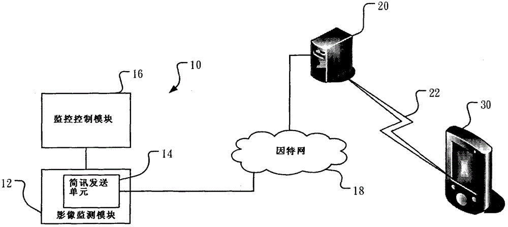
[0034] see Figure 1A , which is a block diagram of a preferred embodiment of the present invention. As shown in the figure, the remote monitoring device 10 of the present invention is installed in a public environment, such as living room, bedroom, and workplace at home. The remote monitoring device 10 includes an image monitoring module 12 and a short message sending unit 14 . In addition, the remote monitoring device 10 of the present invention further includes a monitoring control module 16 .

[0035] The short message sending unit 14 is arranged on the image monitoring module 12, and the short message sending unit 14 is connected to a short message server 20 through an Internet 18, wherein the short message sending unit 14 of th...


PUM


Abstract

The present invention provides a remote monitoring apparatus and method thereof. A short message sending unit is disposed in an image monitoring module used for detecting if the environment image is abnormal. When an abnormal environment image is detected, a corresponding monitoring message is produced. The short message sending unit produces an assigned short message according to the monitoring message produced by the image monitoring module and transmits the assigned short message to a short message server. The short message server then transmits the assigned short message to the corresponding mobile communication terminal via a network interface according to a user's name contained in the assigned short message. Accordingly, the present invention reduces the transmission platforms during the process a short message is sent from the image monitoring module to the mobile communication terminal, and thus reducing the delay of the short message and improving the efficiency of surveillance notification.

Description

technical field [0001] The present invention relates to a monitoring device and its method, in particular to a remote monitoring device and its method. Background technique [0002] Today's social security is deteriorating, and the anti-theft security industry has emerged to assist the government in maintaining security. In order to increase the value of security, the security industry provides more diversified services, such as remote monitoring. The general remote monitoring device is controlled by the on-site computer security host computer to control the anti-theft and video surveillance system and other devices, and is connected with the computer interrogation switchboard of the self-established security control center and the police unit that accepts the report through the telecommunication transmission line, and After the computer security host program processes each sensing signal, it can automatically generate security systems such as report, remote monitoring, reco...

Claims


Application Information

Patent Timeline
Patent Type & Authority Applications(China)
IPC IPC(8): H04N7/18H04L12/58
CPCH04N7/18H04N7/185H04L51/38H04L12/58H04L51/58
Inventor 周山琳
Owner TAIWAN WELL GUARDER
Why Eureka
Try Eureka