

Electrode holder for electric glass melting
A technology for electrode fixtures and glass melting furnaces, applied in ohmic resistance electrodes, glass production, glass furnace equipment, etc., can solve problems such as failure and electrode shrinkage
- Summary
- Abstract
- Description
- Claims
- Application Information
AI Technical Summary
Problems solved by technology
Method used
Image

Examples
Embodiment Construction
[0019] In the following detailed description, for purposes of explanation and not limitation, example embodiments disclosing specific details are set forth in order to provide a thorough understanding of the present invention. However, it will be apparent to those skilled in the art having the benefit of this disclosure that the invention may be practiced in other embodiments that depart from these specific details disclosed herein. Moreover, descriptions of well-known devices, methods and materials may be omitted so as not to obscure the present invention. Finally, where applicable, like reference numbers refer to like elements.
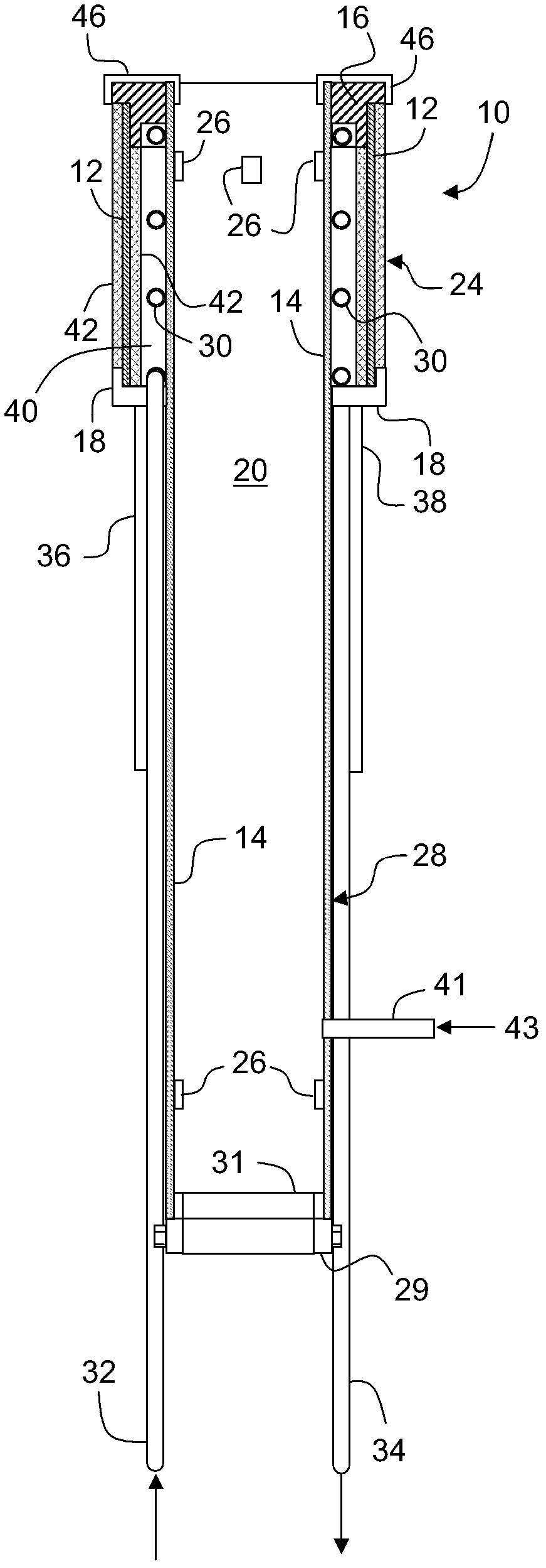
[0020] figure 1 A longitudinal cross-sectional view of an electrode holder 10 according to one embodiment is depicted. The outer shape of the electrode holder 10 is generally cylindrical and includes an outer wall 12 , an inner wall 14 , an annular nose member 16 and an annular rear member 18 . The outer wall 12 and the inner wall 14 are tubular....
PUM
| Property | Measurement | Unit |
|---|---|---|
| thickness | aaaaa | aaaaa |
Abstract
Description
Claims
Application Information