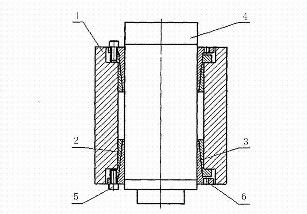
Tool structure of electric spindle

A technology of electric spindle and tooling, which is applied in the direction of metal processing equipment, etc., can solve the problems of uneven installation and clamping deformation, positioning accuracy and positioning stability, etc., and achieve the effect of small clamping deformation, easy deformation and reliable clamping

CN102764901AInactive Publication Date: 2012-11-07CHANGZHOU TPD PRECISION MACHINERY
0 Cites 1 Cited by

Patent Information

Authority / Receiving Office
CN · China
Patent Type
Applications(China)
Current Assignee / Owner
Publication Date
2012-11-07
Estimated Expiration
Not applicable · inactive patent

Smart Images

  • Figure 1
    Figure 1
Patent Text Reader

Abstract

The invention discloses a tool structure of an electric spindle. The tool structure comprises a base, an outer taper sleeve and an inner taper sleeve, the outer taper sleeve and the inner taper sleeve are matched with each other to form a taper ring, the inner taper sleeve is sleeved on the outer side of the electric spindle, the base is sleeved on the outer side of the outer taper sleeve, a locking screw is arranged on the base, and the taper ring is axially locked by the locking screw. The outer taper sleeve and the inner taper sleeve have small taper angles, a taper surface of the taper ring and a threaded surface of the screw are used for double force increase, the force increasing ratio is high, self-locking can be realized, clamping is reliable, a taper ring group with an opening is easy and uniform in deformation, can keep good surface contact with (the electric spindle) internally and externally matched cylindrical surfaces and is low in clamping deformation and high in positioning precision and clamping rigidity, and the taper ring with two grouped ends has double support and fine clamping stability.
Need to check novelty before this filing date? Find Prior Art

Description

technical field

[0001] The invention relates to a tooling structure, in particular to a tooling structure of an electric spindle Background technique

[0002] As a strategic industry, machine tool equipment has always been highly valued by countries all over the world. In recent years, machine tool equipment has developed towards high speed, high precision and intelligence. The trend of high speed main drive of machine tools is to adopt "zero transmission" technology, that is, to use electric spindle integrated with spindle and motor. At present, electric spindle is in the machine tool industry The application of the electric spindle is quite common. As an independent functional part of the machine tool, the user installs and uses it on the machine tool after selecting and purchasing. The problems of the current common installation and positioning methods are: the positioning accuracy and positioning stability are not high, and the installation clip The tight deformation is...

Examples

Embodiment Construction

[0011] In order to deepen the understanding of the present invention, the present invention will be further described below in conjunction with the embodiments and accompanying drawings. The embodiments are only used to explain the present invention and do not constitute a limitation to the protection scope of the present invention.

[0012] figure 1 An embodiment of the tooling structure of an electric spindle of the present invention is shown, including a base 1, an outer tapered sleeve 2 and an inner tapered sleeve 3, the outer tapered sleeve 2 and the inner tapered sleeve 3 are matched to form a tapered ring, and the The inner taper sleeve 3 is sleeved on the outside of the electric spindle 4, the base 1 is sleeved on the outside of the outer taper sleeve 2, and a locking screw 5 is arranged on the base, and the locking screw 5 axially locks the cone ring, and the base 1 is provided with a small hole 6 for dismounting the outer taper sleeve 2 and the inner taper sleeve 3.