
An omnidirectional antenna and electronic equipment

An omnidirectional antenna and feeding technology, applied in the direction of the antenna, the antenna grounding device, the antenna grounding switch structure connection, etc., can solve the problems of increased bit error rate, poor QoS service quality, and reduced data transmission capacity of wireless links. Impedance adjustable effect

Active Publication Date: 2015-08-19
KUANG CHI INST OF ADVANCED TECH
View PDF3 Cites 0 Cited by
  • Summary
  • Abstract
  • Description
  • Claims
  • Application Information

AI Technical Summary

Problems solved by technology

The wireless user equipment may be susceptible to other access points, other wireless communication devices, changes or interference in the wireless link environment between the access point and the remote receiving point, etc.
This interference may greatly reduce the data transmission capacity of the wireless link, or greatly increase the bit error rate and poor QoS service quality, which may cause users to be unbearable

Method used


Image

  • An omnidirectional antenna and electronic equipment
  • An omnidirectional antenna and electronic equipment

Examples


Embodiment approach

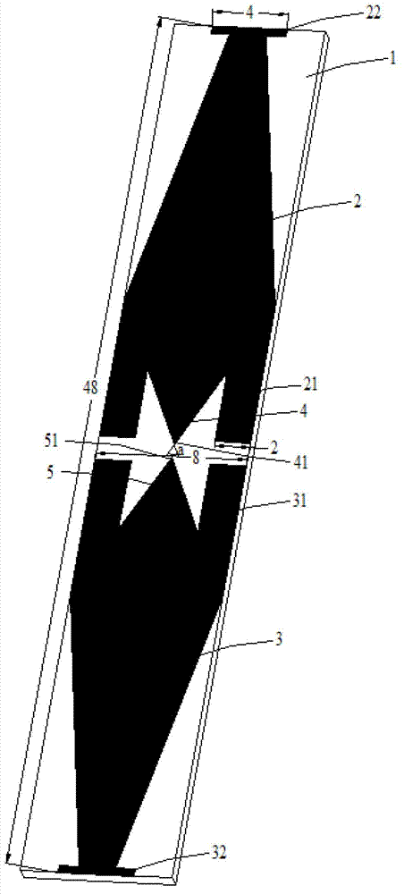
[0023] see figure 1 Shown is an embodiment of the omnidirectional antenna of the present invention, the omnidirectional antenna includes a dielectric substrate 1, a first radiating unit 2, a second radiating unit 3, a feeding unit 4 and a grounding unit 5, and the dielectric substrate 1 has two On the surface, the first radiating unit 2 , the second radiating unit 3 , the feeding unit 4 and the grounding unit 5 are all arranged on the same surface of the dielectric substrate 1 . The first radiating unit 2 and the second radiating unit 3 are symmetrically distributed on the dielectric substrate 1 with respect to the vertical plane passing through the center line between the two, and the first radiating unit 2 and the second radiating unit 3 have the same shape and size. It is a combination shape of a trapezoid and a rectangle in contact with the bottom edge of the trapezoid. A first radiation unit branch 21 is set on the first radiation unit 2. The first radiation unit branch 2...


PUM


Abstract

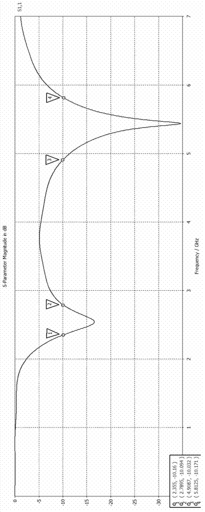
The invention provides an omnidirectional antenna which comprises a dielectric substrate, a first radiation unit, a second radiation unit, a feeding unit and a grounding unit. The first radiation unit is arranged on a surface of the dielectric substrate and is in the shape of a combination of a trapezoid and a rectangle connecting with the bottom side of the trapezoid; the second radiation unit is in the shape of a combination of a trapezoid and a rectangle contacting with the bottom side of the trapezoid, and is opposite to the first radiation unit; the feeding unit is triangular, and one side of the feeding unit is connected with the first radiation unit; the grounding unit is triangular, one side of the grounding unit is connected with the second radiation unit, and the grounding unit is opposite to the feeding unit; and the first radiation unit and the second radiation unit respectively comprise a first radiation unit branch and a second radiation unit branch. The omnidirectional antenna is a dual-frequency broadband omnidirectional antenna and can work in two frequency bands, impedance of the omnidirectional antenna is adjustable, the bandwidth and the center frequency point of the omnidirectional antenna also can be adjusted as needed, electronic equipment comprising the omnidirectional antenna can transmit wireless signals on the basis of IEEE802.11, and the requirement on wireless signal coverage within a certain region can be met.

Description

technical field [0001] The invention relates to the field of wireless communication equipment, more specifically, to an omnidirectional antenna and electronic equipment using the omnidirectional antenna. Background technique [0002] In the wireless communication system, users have requirements for continuous improvement of data throughput, high QoS service quality and strong anti-interference ability of the wireless communication system. For example, in communication systems such as IEEE802.11a / g / h, a wireless access point (AP) transmits data with one or more wireless user equipments through a wireless link. The wireless UE may be susceptible to other access points, other wireless communication devices, changes or interference in the wireless link environment between the access point and the remote receiving point, and the like. The interference may greatly reduce the data transmission capability of the wireless link, or greatly increase the bit error rate and poor QoS ser...

Claims


Application Information

Patent Timeline
Patent Type & Authority Patents(China)
IPC IPC(8): H01Q1/38H01Q1/48H01Q1/50H01Q5/10
Inventor 刘若鹏徐冠雄李双双邱奇岳艳涛
Owner KUANG CHI INST OF ADVANCED TECH
Learn More