
Magnetic antenna

A magnetic antenna and coil technology, applied in the field of train communication, can solve the problems of interference of magnetic rods, cannot work normally, large size, etc., and achieve the effect of overcoming the problem of side lobes

Pending Publication Date: 2022-03-25
BEIJING RAILWAY SIGNAL
View PDF0 Cites 0 Cited by
  • Summary
  • Abstract
  • Description
  • Claims
  • Application Information

AI Technical Summary

Problems solved by technology

[0004] There are three signals in the application, one of which needs to correspond to a magnetic rod, and three magnetic rod antennas are needed to realize this function, which is relatively large
Three-way signals coexist in one magnetic rod and interfere with each other, so it cannot work normally

Method used


Image

  • Magnetic antenna
  • Magnetic antenna
  • Magnetic antenna

Examples


Embodiment 1

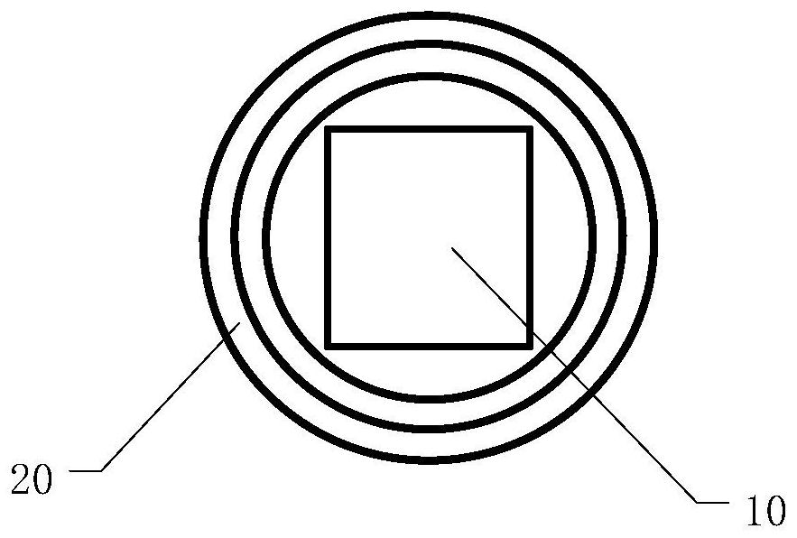
[0020] figure 1 It is a front view of a magnetic antenna according to an embodiment of the present application.

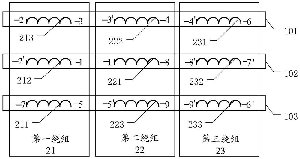
[0021] Such as figure 1 As shown, the magnetic antenna provided in this embodiment is applied to a communication system on a train to realize the signal transmission function of vehicle-ground communication. For providing multiple information channels, the magnetic antenna specifically includes a magnetic rod 10 and multiple windings 20, and the multiple windings are sequentially socketed on the magnetic rod according to preset distances. Each winding in the present application includes a plurality of relatively independent coils, and the coils have a layered structure, that is, each winding consists of wire layers distributed in layers from inside to outside or from outside to inside. Multiple coils may have the same or different impedances.

[0022] In view of the fact that the number of information channels for communication between the vehicle and the ground...


PUM


Abstract

The invention discloses a magnetic antenna. The magnetic antenna comprises a magnetic rod and a plurality of windings sleeving the magnetic rod. Each winding comprises a plurality of coils which are arranged in a layered manner from inside to outside, and the number of the coils on each winding is the same as that of the windings; the plurality of coils are connected into a channel according to a preset connection direction, the number of the coils forming the channel is the same as that of the windings, and the coils belong to different windings. According to the multi-channel magnetic bar, multiple channels coexist on one magnetic bar through a special structure, and mutual inductance does not exist. The special-shaped structure enables the side lobe of the magnetic antenna to be small, and the side lobe problem is solved. And the impedance of the channel is adjustable through the wire diameter of the coil.

Description

technical field [0001] The present application relates to the technical field of train communication, and more specifically, relates to a magnetic antenna. Background technique [0002] The magnetic antenna is widely used in the railway signal system. It is installed on the train. The three signals share the same antenna. The communication between the train and the ground is carried out through the energy conversion of the electromagnetic field, so as to realize the automatic control of the train. [0003] Due to the natural distribution of the magnetic field lines, the electromagnetic waves emitted by the magnetic antenna will form a main lobe and a side lobe. The magnetic field strength of the side lobe is slightly smaller than that of the main lobe. The side lobe is sometimes mistaken for the main lobe, and the application will work normally for the antenna. make an impact. The current method is to do processing on the software, increase the threshold and acceptable rang...

Claims


Application Information

Patent Timeline
Patent Type & Authority Applications(China)
IPC IPC(8): H01Q7/06
CPCH01Q7/06
Inventor 仝师伟邢跃飞李志勇安成龙车萧羽
Owner BEIJING RAILWAY SIGNAL
Learn More