
Novel ground polisher structure

A polishing machine and floor technology, which is applied to surface polishing machine tools, grinding/polishing equipment, machine tools suitable for grinding workpiece planes, etc., can solve the problems of labor stress and heavy labor, and meet the requirements of leveling and polishing the ground 、To overcome the effect of labor stress and labor load

Inactive Publication Date: 2012-11-21
刘新海
View PDF0 Cites 0 Cited by
  • Summary
  • Abstract
  • Description
  • Claims
  • Application Information

AI Technical Summary

Problems solved by technology

[0003] The purpose of the present invention is to provide a new structure of floor polishing machine, which can meet and facilitate the needs of leveling and polishing the ground in the labor process of building decoration, and overcome the labor stress existing in the existing ground leveling and polishing. Defects with a relatively large amount of labor

Method used


Image

  • Novel ground polisher structure

Examples


Embodiment Construction

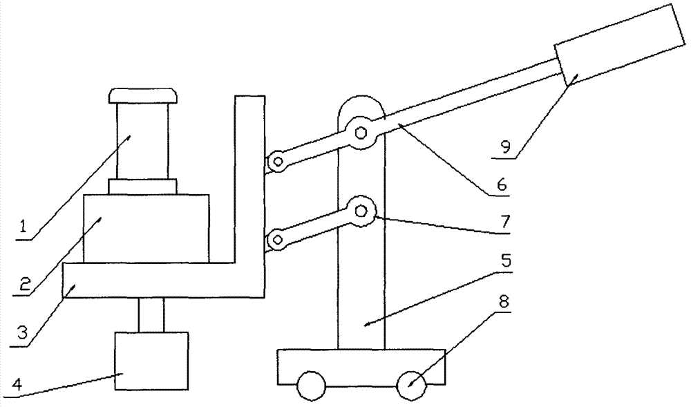
[0010] Wheel 8 is installed on the bottom of vehicle frame 5 to ensure that under the action of external force, wheel 8 can drive vehicle frame 5 to walk freely, and the parts of L-shaped frame 3, short connecting rod 6, long connecting rod 7 and vehicle frame The parts of 5 are hinged with each other to form a parallelogram mechanism, and the handle 9 is set at the end of the long connecting rod 7 at the right part of the vehicle frame 5, and the gear box 2 is installed and fixed on the horizontal position of the L-shaped frame 3, and the motor 1 and the gear box 2 The structural form of installation and combination, the grinding head 4 is installed and fixed on the output shaft of the gear box 2.


PUM


Abstract

Disclosed is a novel ground polisher structure. Wheels are mounted at the bottom of a frame, the wheels can drive the frame to move freely under the action of external force, portions of an L-shaped rack, a short connecting rod, a long connecting rod and the frame are mutually hinged to form a parallelogram mechanism, a handle is sleeved at the end arranged on the right of the frame on the long connecting rod, a gearbox is fixedly installed on the horizontal portion of the L-shaped rack, the motor and the gearbox are installed and combined into an integrated structure, and a grinding head is fixedly installed on an output shaft of the gearbox.

Description

technical field [0001] The invention relates to a structure of a floor polishing machine, in particular to a structure of a novel floor polishing machine, and belongs to the technical field of decoration machinery and equipment. Background technique [0002] In the labor process of building decoration, leveling and polishing the ground is a labor with a relatively large amount of labor and labor stress. At present, in the labor process of polishing the ground, manual or hand-held small electric drills are mainly used to install polishing heads. This kind of labor method not only has extremely low production efficiency, but also has high labor intensity. Contents of the invention [0003] The purpose of the present invention is to provide a new structure of floor polishing machine, which can meet and facilitate the needs of leveling and polishing the ground in the labor process of building decoration, and overcome the labor stress existing in the existing ground leveling an...

Claims


Application Information

Patent Timeline
Patent Type & Authority Applications(China)
IPC IPC(8): B24B7/18B24B29/02
Inventor 刘新海
Owner 刘新海
Learn More