
Piston type hidden hinge capable of being adjusted in six directions

A hidden hinge technology, applied in the field of hidden hinges, can solve problems such as time-consuming, insufficient hinge bearing capacity, and easy sagging affecting opening, etc., to achieve the effects of increasing installation difficulties, prolonging service life, and strengthening bearing capacity

Inactive Publication Date: 2012-11-28
SHENZHEN CHANGEN IND
View PDF4 Cites 7 Cited by
  • Summary
  • Abstract
  • Description
  • Claims
  • Application Information

AI Technical Summary

Problems solved by technology

[0003] The purpose of the present invention is to overcome the shortcomings of the existing hinges, which are insufficient in bearing force during use, easy to sag to affect opening, and take a lot of time to adjust during installation and use, and to invent a piston-type six-way adjustable hidden hinge. The adjustment mechanism on the hinge can quickly eliminate the position error between the door and window sash and the door and window frame, and easily complete the installation and long-term use of the door and window

Method used


Image

  • Piston type hidden hinge capable of being adjusted in six directions
  • Piston type hidden hinge capable of being adjusted in six directions
  • Piston type hidden hinge capable of being adjusted in six directions

Examples


Embodiment Construction

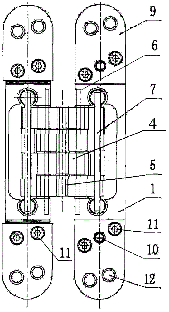
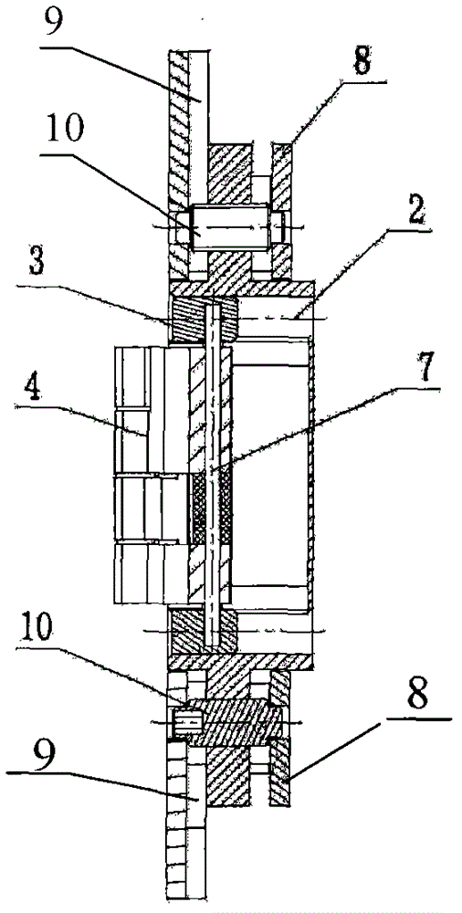
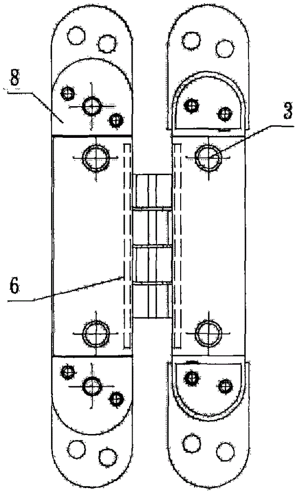
[0014] Such as figure 1 figure 2 image 3 As shown, the piston-type hidden hinge that can be adjusted in six directions includes two bases 1 on the left and right. The base 1 is provided with two column-shaped rail-fixing grooves 2 up and down, and the column-shaped rail-fixing groove 2 is provided with Cylindrical movable plug 3; there are four connecting pieces 4, two connecting pieces 4 are respectively arranged on the left and right bases 1 through two attached shafts 6, and the other two connecting pieces 4 are set on the left and right bases 1 through two moving shafts 7 Installed on the left and right column-type movable plugs 3; the connecting piece 4 on the left base 1 and the connecting piece 4 on the right base 1 are hinged together through the main shaft 5; the surfaces at both ends of the base 1 are respectively provided with adjustment plates 8 and movable plate 9, front and rear adjustment screws 10 are provided between the adjustment plate 8 and the movable ...


PUM


Abstract

The invention provides a hinge used on a door or a window and particularly relates to a piston type hidden hinge capable of being adjusted in six directions. The piston type hidden hinge capable of being adjusted in the six directions comprises a left base and a right base; an upper columnar track determination groove and a lower columnar track determination groove are arranged on the bases; a columnar movable plug is arranged inside each columnar track determination groove; the piston type hidden hinge capable of being adjusted in the six directions further comprises four connection sheets; two of the four connection sheets are respectively arranged on the left base and the right base through two adhesion shafts, and the other two connection sheets are mounted in the columnar movable plugs on the left base and the right base through two movable shafts; the connection sheet on the left base and the connection sheet on the right base are integrally hinged through a spindle; the surfaces of both ends of the bases are respectively provided with an adjusting board and a movable board; a front-and-back adjusting screw is arranged between the adjusting board and the movable board; an upper-and-lower adjusting screw is arranged on the movable board on the right base; and a mounting hole is arranged on the movable board. With the adoption of the piston type hidden hinge capable of being adjusted in the six directions comprises provided by the invention, the bearing force of the hinge is enhanced; the hinge is naturally switched on without resistance, and the service life is prolonged; and the hinge can be adjusted in the six directions, i.e. a front direction, a back direction, an upper direction, a lower direction, a left direction and a right direction without dismounting the door and frames, and can be opened by 180 degrees.

Description

technical field [0001] The invention relates to a hinge for doors and windows, in particular to a piston-type concealed hinge that can be adjusted in six directions. Background technique [0002] A hinge, also known as a hinge, is a mechanical device used to connect two solids and allow rotation between them, the most common being a hinge installed on doors and windows. Due to the unavoidable problems of insufficient force and sagging affecting the opening of doors and windows during the use process, and also because of various reasons such as the error of the size and shape of the door opening, the error of the processing accuracy of the door itself, and the unskilled installation workers, etc., the door leaf and the door frame appear. The uneven interval between the doors affects the opening and closing of the door, and a lot of time and energy have to be spent on adjustments during installation, adjustment and use. Contents of the invention [0003] The purpose of the ...

Claims


Application Information

Patent Timeline
Patent Type & Authority Applications(China)
IPC IPC(8): E05D7/04E05D3/06E05D5/04
Inventor 赖文坤
Owner SHENZHEN CHANGEN IND
Learn More