
MEMS display with touch function

A micro-electro-mechanical and display technology, which is applied in the field of micro-electro-mechanical displays with touch functions, can solve the problems that the thickness of the display module cannot be reduced, energy consumption, etc.

Active Publication Date: 2016-05-04
信宸科技发展(广州)有限公司
View PDF8 Cites 0 Cited by
  • Summary
  • Abstract
  • Description
  • Claims
  • Application Information

AI Technical Summary

Problems solved by technology

However, the traditional liquid crystal display needs to use a backlight, which not only consumes energy, but also the thickness of the overall display module cannot be reduced due to the backlight. When used in light, thin, short, and small handheld devices, it will become a bottleneck where the

Method used

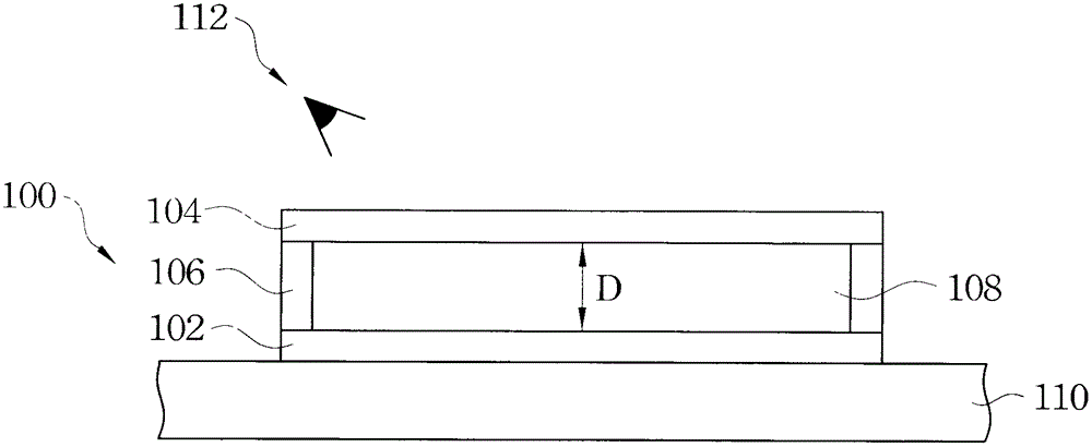
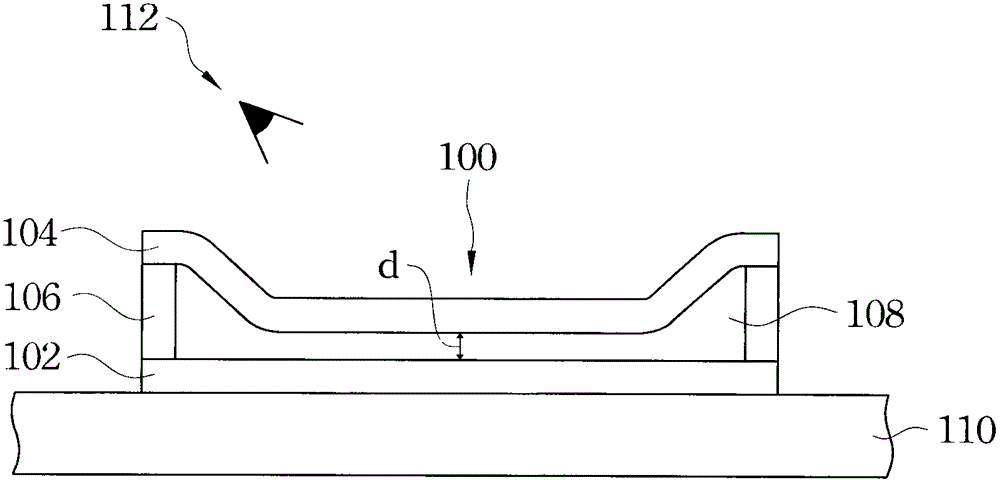
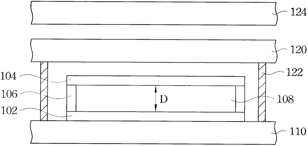

Image

  • MEMS display with touch function
  • MEMS display with touch function
  • MEMS display with touch function

Examples


Embodiment Construction

[0118] In order to achieve a more user-friendly operation, many electronic products have changed from traditional input devices such as keyboards or mice to use touch panels as input devices. One of the main technical features of the present invention is to integrate the touch function into an optical interference display system or into a micromirror array display system to become a micro-electromechanical display device with a touch function.

[0119] According to the detection method, the touch panel has electromagnetic induction method, optical induction method, ultrasonic induction method, capacitive induction method, resistance induction method, pressure induction method or a combination of the above multi-mode induction methods. Among them, the resistance sensing type, lightly pressing with a finger or other contacts will produce a voltage change, and the touch position can be distinguished by detecting the change of the voltage. In the ultrasonic sensing method, sound w...


PUM


Abstract

The invention discloses a micro electromechanical display possessing touch control function which at least includes a first substrate which is provided with a control array, a touch control unit, and multiple micro electromechanical display units arranged on the first substrate. The control array controls the multiple micro electromechanical display units.

Description

technical field [0001] The present invention relates to a micro-electro-mechanical display, and in particular to a micro-electro-mechanical display with a touch function. Background technique [0002] Due to the characteristics of small size and light weight, the flat panel display has great advantages in the portable display device and the display market for small space applications. Currently, the mainstream flat panel display device in the market is a liquid crystal display (Liquid Crystal Display, LCD). However, the traditional liquid crystal display needs to use a backlight, which not only consumes energy, but also the thickness of the overall display module cannot be reduced due to the backlight. When used in light, thin, short, and small handheld devices, it will become a bottleneck where. Therefore, a new type of display manufactured by Micro-Electro-Mechanical Systems (MEMS) system has been developed. MEMS is an industrial technology that combines microelectronic...

Claims


Application Information

Patent Timeline
Patent Type & Authority Patents(China)
IPC IPC(8): G02B26/00G06F3/041
Inventor 刘鸿达
Owner 信宸科技发展(广州)有限公司
Learn More