Hand shank component of switch device, and switch device

A switch device and handle technology, applied in the direction of contact operating parts, etc., can solve problems such as misoperation and inadvertent rotation of the handle

Active Publication Date: 2015-04-29
SIEMENS AG
View PDF3 Cites 0 Cited by
  • Summary
  • Abstract
  • Description
  • Claims
  • Application Information

AI Technical Summary

Problems solved by technology

However, in some cases, it may cause misoperation due to unexpected gear switching
For example, the closing gear is adjacent to the opening gear, and the test gear is set on the side of the opening gear. When turning the handle to switch from the closing gear to the opening gear, the handle may be damaged due to special circumstances such as excessive force. Accidentally turning to the position of the test gear, causing misoperation

Method used


Image

  • Hand shank component of switch device, and switch device
  • Hand shank component of switch device, and switch device
  • Hand shank component of switch device, and switch device

Examples


Embodiment Construction

[0038] In order to have a clearer understanding of the technical features, purposes and effects of the invention, the specific embodiments of the present invention are now described with reference to the accompanying drawings, in which the same reference numerals represent components with the same or similar structures but the same functions. The components in the drawings are only used to illustrate and exemplify the content related to the present invention, but not their real scale and / or actual structure.

[0039] In this article, "axial", "radial", "circumferential", "above", "below" and so on are only used to indicate the positional relationship between related parts, rather than to limit the absolute position in the geometric sense, and they include any engineering margin of error.

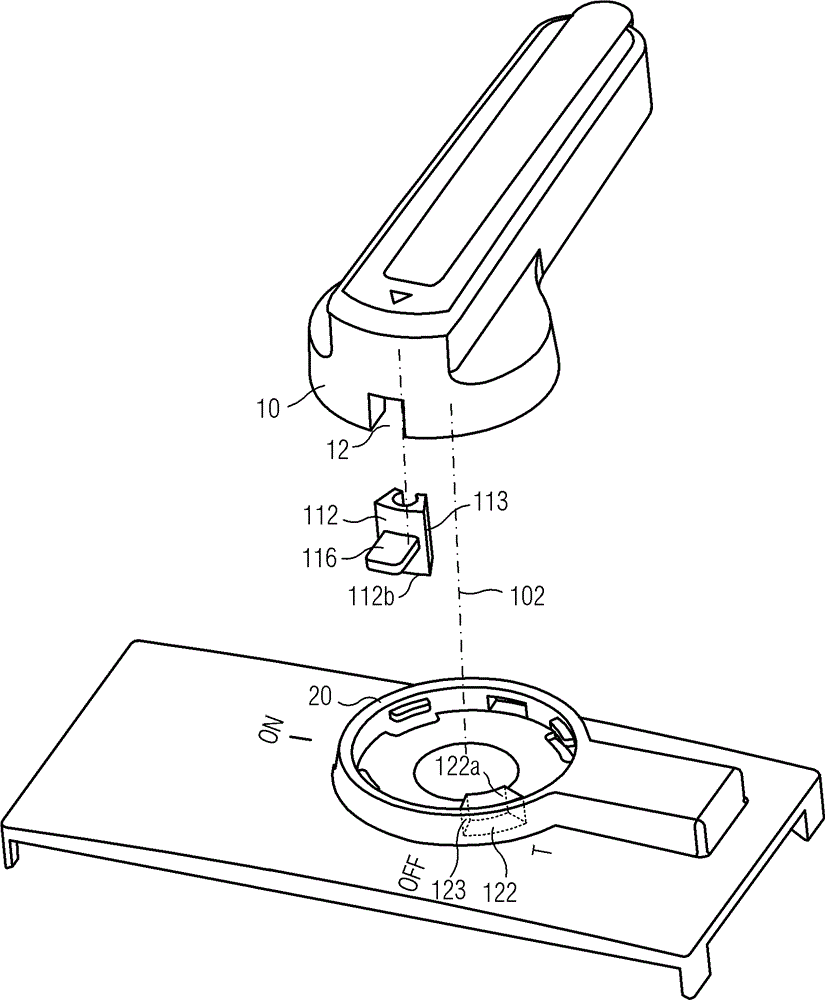
[0040] figure 1 is an exploded perspective view of a schematic embodiment of a handle assembly of a switchgear. Such as figure 1 As shown, the handle assembly of the switch device include...


PUM


Abstract

The switching unit has stop units (112,122) that are at a support surface (20) and an edge circumference of a handle (10). The surfaces (113,123) of stop units abut during locking position. The abutting end surfaces of the stop units are resolved from each other about rotational axis in axial or radial direction using a release unit (116) attached to the stop unit (122) during unlocking position, so that handle is rotated. An independent claim is included for a switching device.

Description

technical field [0001] The invention relates to a handle assembly of a switch device, in particular to a handle assembly capable of preventing misuse, and also relates to a switch device with the handle assembly capable of preventing misoperation. Background technique [0002] In the switchgear, the commonly used switch controlled by turning the handle generally has closing (ON), opening (OFF) and test (TEST) gears, and the gears can be switched by turning the handle. However, in some cases, misoperation may occur due to unexpected gear shifting. For example, the closing gear is adjacent to the opening gear, and the test gear is set on the side of the opening gear. When the handle is turned from the closing gear to the opening gear, the handle may be damaged due to special circumstances such as excessive force. Accidentally turn to the position of the test gear, causing misoperation. Contents of the invention [0003] The purpose of the present invention is to provide a ...

Claims


Application Information

Patent Timeline
Patent Type & Authority Patents(China)
IPC IPC(8): H01H3/20
CPCH01H3/06
Inventor 蒲恩强陈德州宋磊宋建康姜禹姜晓军段新高李大意刘明华
Owner SIEMENS AG
Why Eureka
Try Eureka