Changeover valve

A switching valve and switching tube technology, applied in the field of switching valves, can solve problems such as automatic reset

Active Publication Date: 2012-12-05
NEOPERL
View PDF6 Cites 8 Cited by
  • Summary
  • Abstract
  • Description
  • Claims
  • Application Information

AI Technical Summary

Problems solved by technology

If three outlets are exceptionally required in the hygienic area, rotary-actuated switc

Method used


Image

  • Changeover valve
  • Changeover valve
  • Changeover valve

Examples


Embodiment Construction

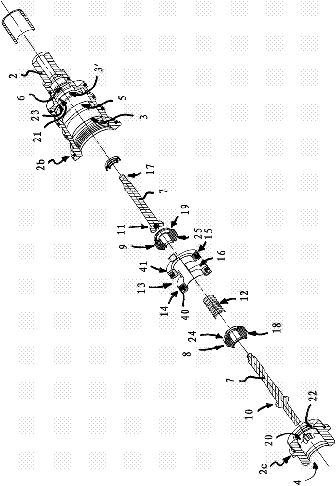
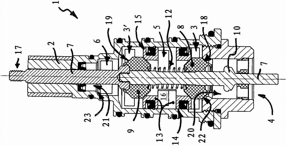
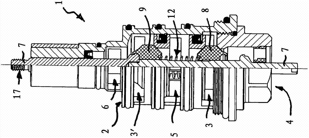
[0032] Figures 1 to 11 A changeover valve 1 configured as a 4-position, 3-way valve is shown. The inlet of the switchover valve 1 is connected, for example, to a water supply, while the outlet of the switchover valve 1 leads selectively to a bathtub outlet fitting, a flexible hand shower or, for example, to a fixed spray head.

[0033] Switching valve 1 has the Figures 1 to 4 The valve housing 2 shown in detail in , has two inlet holes 3, 3' serving as inlets and three outlet holes 4, 5 and 6 serving as outlets. The valve housing 2 can be constructed in one or more parts; the valve housing 2 is here constructed in two parts and has a fitting housing 201 (see Figures 5 to 8 ) into the cartridge 2b and the threaded joint 2c used as the end-side termination of the fitting housing 201 (see Figures 1 to 4). Of the three outlet holes 4, 5, 6, each outlet hole can be selectively assigned to the inlet holes 3, 3' On the switching shaft 7 two sealing elements 8 , 9 are gu...


PUM


Abstract

The invention relates to a changeover valve comprising a valve housing, two sealing elements, and a switching tube, wherein an axial actuating movement of the changeover shaft can be transferred at least to one of the two sealing elements in such a way that either both sealing elements bear with outer circumferential sealing surfaces on the sealing surfaces of the valve housing that surround a fluid passage and one of the sealing elements closes the adjacent circumferential front edge of the switching tube with an inner circumferential sealing surface while the other sealing element remains at a distance from the other circumferential front edge of the switching tube, serving as a fluid passage, or both inner circumferential sealing surfaces of the sealing elements bear on the adjacent circumferential front edges of the switching tube while the one sealing element uses the outer circumferential sealing surface thereof to load the adjacent mating sealing surface surrounding the fluid passage, and the other sealing element is spaced apart from the mating sealing surface assigned thereto and surrounding a fluid passage.

Description

technical field [0001] The invention relates to a switching valve, with which different outlets of the switching valve can be selectively assigned to the inlets of the switching valve. Background technique [0002] Switchover valves are already known even in the sanitary field in a variety of designs for selectively passing the water drawn from the pipe network to the bathtub outlet or to the shower head. Furthermore, a changeover valve designed as a 4-position, 3-way valve has been implemented with three outlets, where the first outlet is connected to a hand sprayer, the second outlet is connected to a fixed shower head, and the third outlet can be connected to a tub filling attachment superior. [0003] In known 4 / 3-way valves, one of the three outlets can usually be connected by means of a rotary or translational switching movement. If it is necessary to prioritize an outlet in certain operating states, this is generally achieved in the technical field by means of hydra...

Claims


Application Information

Patent Timeline
IPC IPC(8): F16K11/044F16K27/02
CPCF16K11/0445F16K11/18F16K11/048F16K11/161Y10T137/87064Y10T137/86895
Inventor M·方迈尔
Owner NEOPERL
Why Eureka
Try Eureka