
Lens focusing device

A lens and focusing technology, applied in installation, optics, instruments, etc., can solve problems such as difficulties, poor user experience, difficult focusing operation, etc., and achieve the effect of improving the adjustment feel and improving the user experience

Active Publication Date: 2014-10-15
HISENSE
View PDF5 Cites 0 Cited by
  • Summary
  • Abstract
  • Description
  • Claims
  • Application Information

AI Technical Summary

Problems solved by technology

[0004] However, unlike the ordinary projection equipment placed on the desktop, many projection equipment installed on the wall due to the surrounding conditions of the installation location or the relatively special placement form, if the focusing device is directly drawn out from the side of the projection equipment, the user It will be difficult to perform focusing operations on projection equipment using the above-mentioned focusing device
For example, if the focusing device is arranged on the side of the projection device, and the distance between the side of the projection device and the wall is very small, it will be very difficult for the user to perform focusing operations through the focusing device, and the user experience will be greatly improved. will be bad

Method used


Image

  • Lens focusing device
  • Lens focusing device
  • Lens focusing device

Examples


Embodiment Construction

[0035] In order to make the object, technical solution and advantages of the present invention clearer, the present invention will be further described in detail below with reference to the accompanying drawings and examples.

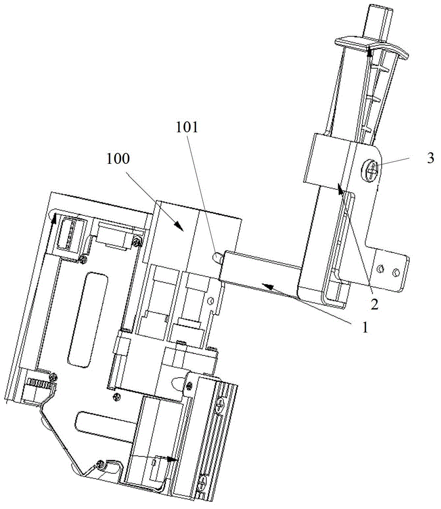
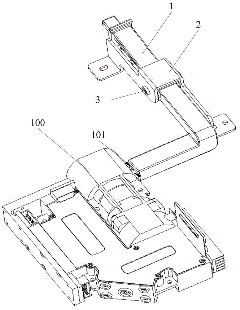
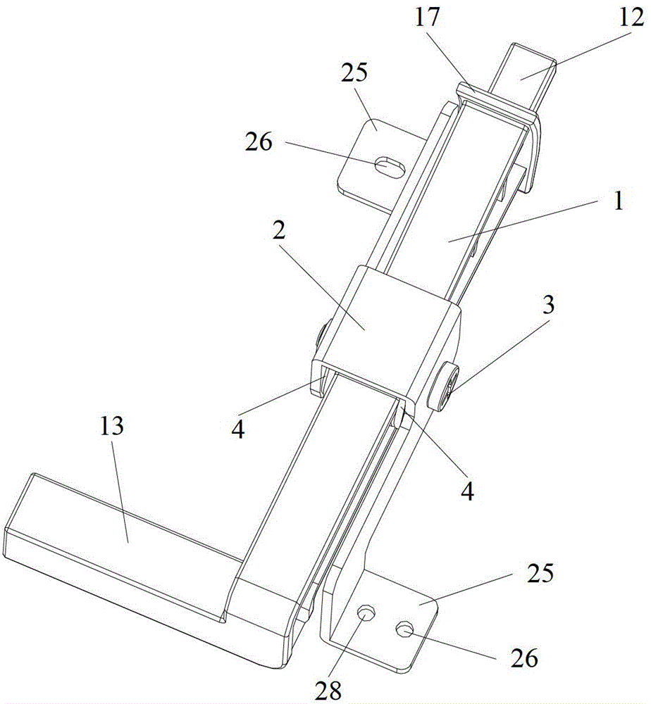
[0036] see Figure 1 to Figure 9 , The lens focusing device in this embodiment includes: a focusing lever 1 , a sheet metal fixing bracket 2 and a bracket screw 3 .

[0037] Wherein, the focusing lever 1 includes: a focusing lever 11, a lever push button 12 arranged at the upper end of the focusing lever 11 and extending out of the housing of the projection device 100, arranged at the lower end of the focusing lever 11 and connected to the The focusing rod 11 is a bending portion 13 at a predetermined angle; the middle part of the focusing rod 11 is provided with a rotating shaft 14, and the middle part of the rotating shaft 14 is provided with a first through hole 15; the bottom of the bending part 13 The end is provided with a lens focusing terminal ...


PUM


Abstract

The invention discloses a lens focusing device. The lens focusing device in the present invention includes: a focusing lever, a sheet metal fixing bracket and a bracket screw. By using the lens focusing device in the present invention, the position of the lever push button in the focusing device can be set at a position where the user can directly operate conveniently, so that the user can conveniently pass the lever of the focusing device The push button directly performs the focusing operation, which greatly improves the user experience. Furthermore, it can also effectively avoid the phenomenon of "empty travel" during the focusing process, and improve the user's adjustment feel.

Description

technical field [0001] The invention relates to focus adjustment technology, in particular to a lens focus adjustment device. Background technique [0002] In order to make full use of the limited space, the projection equipment in the prior art is generally placed on a desktop or hung on a wall, and projects a projected image onto an opposite wall or a projection screen. With different usage scenarios, the location of the projection device and the wall or projection screen on which the projected image is projected will also change accordingly, so the distance between the projection device and the projection wall or projection screen will also change . In order to make the projected picture clearer, it is usually necessary to adjust the focal length of the lens in the projection device accordingly. Therefore, commonly used projection equipment is provided with a corresponding focusing device for adjusting the focal length of the lens. [0003] In many projection devices i...

Claims


Application Information

Patent Timeline
Patent Type & Authority Patents(China)
IPC IPC(8): G02B7/04
Inventor 王自上
Owner HISENSE
Learn More