Stage lighting system for improving uniformity of light spots

A lighting technology, uniformity technology, applied in electric light sources, components of lighting devices, devices used in theaters and circuses, etc. The effect of uniformity

Inactive Publication Date: 2015-11-25
GUANGZHOU HAOYANG ELECTRONICS CO LTD
View PDF6 Cites 5 Cited by
  • Summary
  • Abstract
  • Description
  • Claims
  • Application Information

AI Technical Summary

Problems solved by technology

[0003] Chinese patent CN201410089184.3 discloses that an optical integrator component (that is, a light guide) is set in the optical path, and the pattern component, optical integrator component, and light source component are switched into or out of the optical path as required to achieve pattern effects and beam effects Although this solution can achieve the switching of the two effects, it is realized through the light guide body. The light guide body is a rectangular total reflection structure, and the length is relatively long, which will increase the physical length of the lighting system, and also It is easy to cause light loss. In addition, the position of the light source components in different modes must be adjusted accordingly, and the operation is more complicated.

Method used


Image

  • Stage lighting system for improving uniformity of light spots
  • Stage lighting system for improving uniformity of light spots
  • Stage lighting system for improving uniformity of light spots

Examples


Embodiment 1

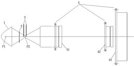
[0045] Such as figure 1 As shown, a stage light optical system for improving spot uniformity includes a light source arranged in sequence along the main optical axis, a reflector 1 and a second optical assembly 4, wherein the stage light optical system also includes a light source arranged on the reflector 1 The first optical component 2 between the first focal point F1 and the second focal point F2, the first optical component 2 is a single array lens.

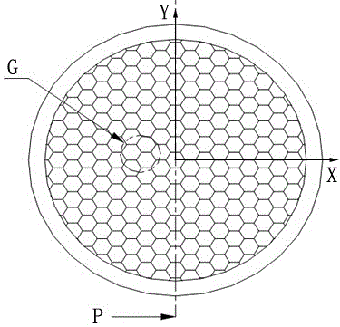
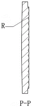
[0046] Such as Figure 2-4As shown, the structure of the array lens is based on glass, and the lens unit is covered on the glass plane. The lens unit is a convex lens unit. The longitudinal section of the lens unit is a regular polygon, preferably a regular hexagon or square. The lens unit mirror surface curvature The same or different, and each lens unit is closely connected together, and the adjacent lens units are seamlessly bonded. The array lens can divide the entire light beam into thin beams and re-superimpose, so th...

Embodiment 2

[0074] In this embodiment, the first optical component is improved on the basis of embodiment 1, and the rest of the structure is the same as that of embodiment 1.

[0075] Such as Figure 9 As shown, the first optical component described in this embodiment is a combination of an array lens and a lens, specifically, it includes a first convex lens 51, a first array lens 21, a second array lens 22, and a second array lens arranged in sequence along the main optical axis. Two convex lenses 52.

[0076] Similarly, the first optical component may also be an array lens and a combination of array lenses, that is, it is composed of several array lenses arranged in sequence along the main optical axis.


PUM


Abstract

The invention relates to a stage lighting system for improving uniformity of light spots. The stage lighting system comprises a light source and a reflection cup which are sequentially arranged along a main optical axis. The stage lighting system further comprises a first optical assembly arranged between a first focus point and a second focus point of the reflection cup. The first optical assembly is a single lens array or a combination of array lenses and lenses or a combination of array lenses and array lenses. The first optical assembly splits a whole optical beam into narrow optical beams and superposes the narrow optical beams again, and light energy is effectively and evenly utilized, and therefore the uniformity of the light spots is improved; and contradiction of optical efficiency and uniformity of an existing stage lighting system is solved, and the uniformity of the light spots is improved under the condition of extremely-low optical losses. The first optical assembly can shift in or out of an optical path through a drive mechanism; when the first optical assembly shifts out of the main optical shaft of the system, the middle optical beam of the formed optical beam is very converged; and when the optical assembly shifts in the main optical shaft, the uniform effect of the light spots is achieved.

Description

technical field [0001] The invention relates to the technical field of stage lamps, in particular to an optical system for stage lights that improves the uniformity of light spots. Background technique [0002] Existing stage lamps can be divided into the following types of lamps according to their functional effects: pattern lamps, beam lamps, and soft lights. Among them, the pattern light can project a pattern effect with a uniform light spot and a strong sense of boundary, the beam light can achieve a beam effect, and the soft light can achieve a uniform light spot effect. These three types of lamps can usually only achieve a single lighting effect. To achieve multiple lighting effects, multiple lamps of various types need to be used together to achieve it, and the operation is very complicated. In order to solve this problem, lamps capable of realizing various light beam effects are also proposed in the prior art. [0003] Chinese patent CN201410089184.3 discloses that...

Claims


Application Information

Patent Timeline
IPC IPC(8): F21S8/00F21V5/04F21W131/105F21W131/406
CPCF21S8/00F21V5/007F21V5/04F21W2131/406F21W2131/105
Inventor 蒋伟楷
Owner GUANGZHOU HAOYANG ELECTRONICS CO LTD
Why Eureka
Try Eureka