Aperture shield incorporating refractory materials

a technology of refractory materials and aperture shields, applied in the field of electron shields, can solve the problems of large localized electron shield heating around the aperture throat, affecting the efficiency of electron shields, and causing “off-focus” x-rays, etc., and achieve the effect of reducing the incidence of failure of electron shields

Active Publication Date: 2009-03-26
VAREX IMAGING CORP
View PDF3 Cites 10 Cited by
  • Summary
  • Abstract
  • Description
  • Claims
  • Application Information

AI Technical Summary

Benefits of technology

[0014]The present invention has been developed in response to the above and other needs in the art. Briefly summarized, embodiments of the present invention are directed to an electron shield for use in an x-ray tube and configured for interposition between an electron emitter and an anode configured to receive the emitted electrons. The electron shield is configured to withstand the elevated temperature produced by electrons backscattered from the anode and incident on the electron shield. This in turn equates to a reduced incidence of failure in the electron shield.
[0015]In one embodiment the electron shield includes a body that defines a bowl-shaped aperture having a narrowed throat segment. The body of the electron shield includes a first body portion, a second body portion, and a disk portion. These portions cooperate to define the bowl and the throat segment. The throat segment and the lower portion of the bowl are composed of a refractory material and correspond with the regions of the electron shield that are impacted by relatively more backscattered electrons from the anode surface. Thus, the electron shield is able to withstand the thermal stress imposed by the backscattered electrons without failure. Additionally, the refractory material assists in smoothing the energy distribution caused by the impacting electrons. This in turn spreads the electron energy absorbed by the shield over a larger area so as to reduce thermal stress to the shield.

Problems solved by technology

One challenge encountered with the operation of x-ray tubes relates to backscattered electrons, i.e., electrons that rebound from the target surface along unintended paths in the vacuum enclosure.
These rebounding, backscattered electrons can impact areas of the x-ray tube where such electron impact is not desired.
These impacts can either cause excess and possibly damaging heating in the impacted component or result in the creation of “off-focus” x-rays that cloud the x-ray image obtained by the x-ray tube.
Either result is undesired.
This results in a relatively large amount of localized electron shield heating about the aperture throat.
Known electron shield designs often prove inadequate in handling such heat without causing damage to the electron shield.
Indeed, at relatively high x-ray tube power settings, electron shield cracking or other failure at or near the aperture throat can be an all-too common occurrence.
Failure of the electron shield in the manner described above is detrimental to tube performance.
Upon failure of the electron shield, the vacuum can be compromised and x-ray production negatively affected.
The x-ray tube can be rendered useless, and must be replaced, often at significant cost.

Method used


Image

  • Aperture shield incorporating refractory materials
  • Aperture shield incorporating refractory materials
  • Aperture shield incorporating refractory materials

Examples


Embodiment Construction

[0026]Reference will now be made to figures wherein like structures will be provided with like reference designations. It is understood that the drawings are diagrammatic and schematic representations of exemplary embodiments of the invention, and are not limiting of the present invention nor are they necessarily drawn to scale.

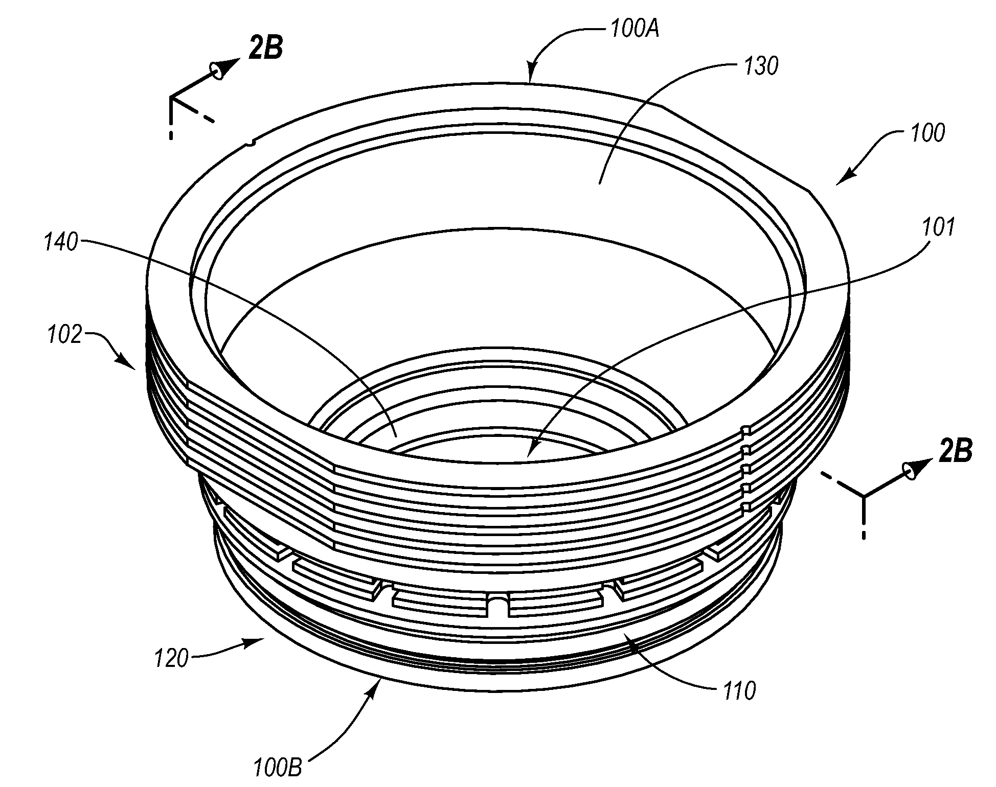
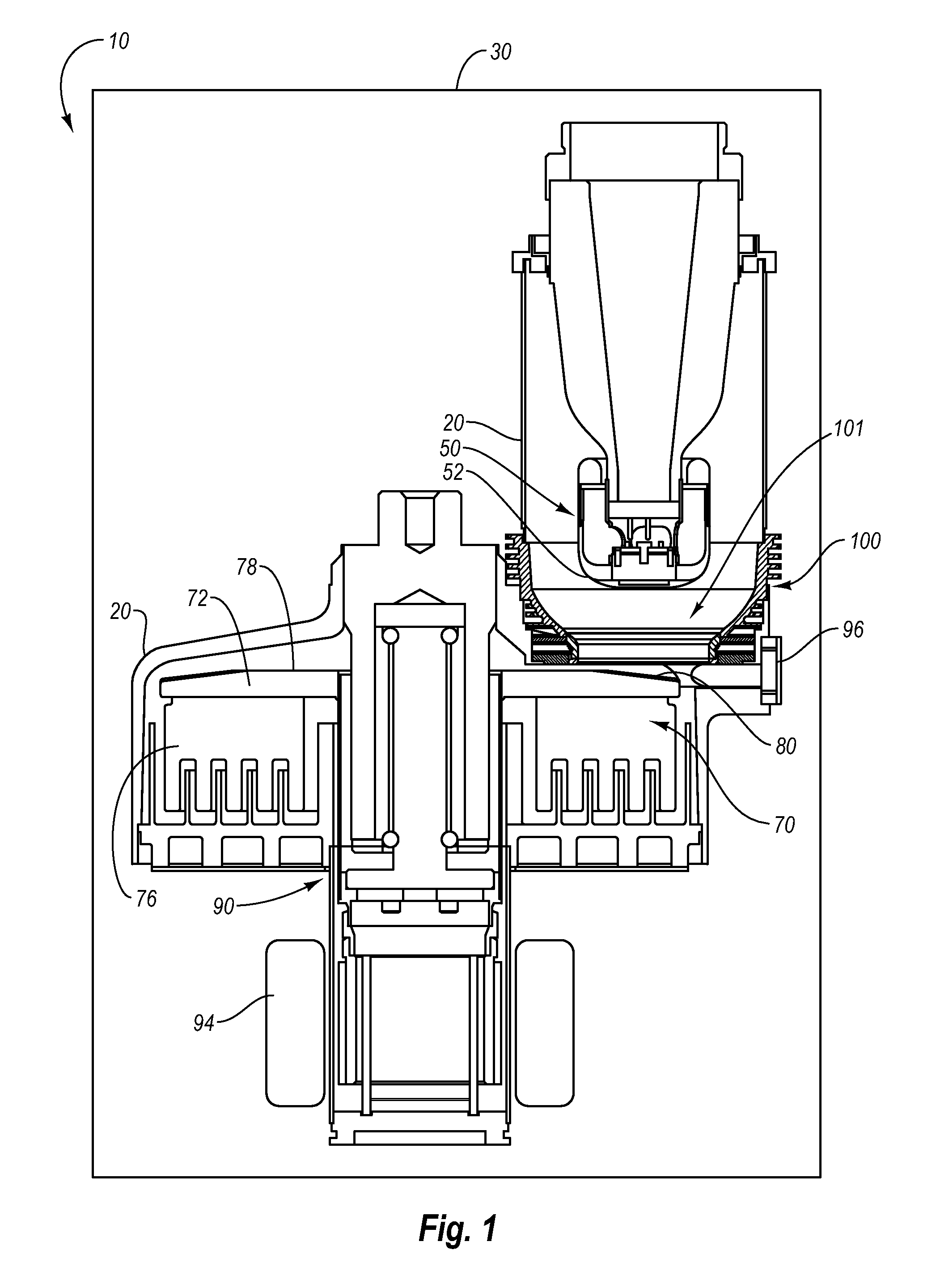
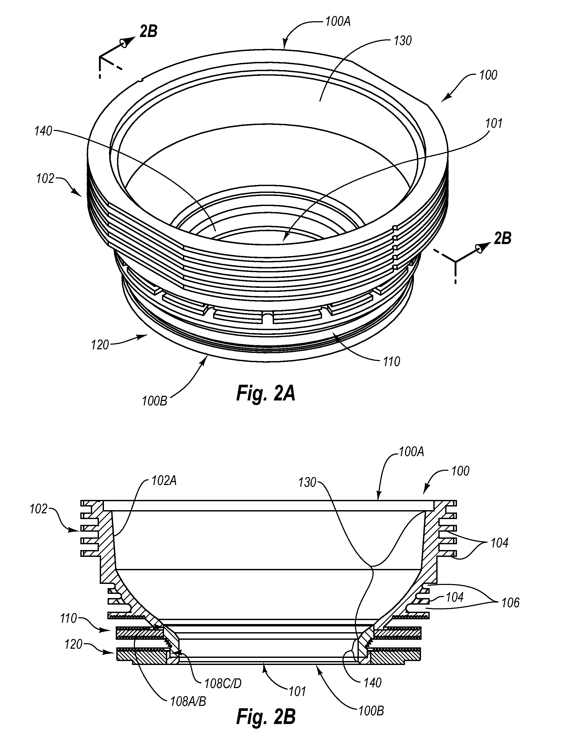
[0027]FIGS. 1-4B depict various features of embodiments of the present invention, which is generally directed to an electron shield for interposition between an electron emitter and an anode configured to receive the emitted electrons, such as in an x-ray tube. Advantageously, the electron shield disclosed in example embodiments of the present invention is configured to withstand the elevated temperature produced by electrons backscattered from the anode and incident on selected portions of the electron shield. This in turn equates to a reduced incidence of failure in the electron shield and in the vacuum envelope, or evacuated enclosure, that it partially de...


PUM

PropertyMeasurementUnit
yield strengthaaaaaaaaaa
refractoryaaaaaaaaaa

Abstract

An x-ray tube electron shield is disclosed for interposition between an electron emitter and an anode configured to receive the emitted electrons. The electron shield is configured to withstand the elevated levels of heat produced by electrons backscattered from the anode and incident on the electron shield. This in turn equates to a reduced incidence of failure in the electron shield. In one embodiment the electron shield includes a body that defines a bowl-shaped aperture having a narrowed throat segment. The body of the electron shield includes a first body portion, a second body portion, and a disk portion. These portions cooperate to define the bowl and the throat segment. The throat segment and the lower portion of the bowl are composed of a refractory material and correspond with the regions of the electron shield that are impacted by relatively more backscattered electrons from the anode surface.

Description

BACKGROUND[0001]1. Technology Field[0002]The present invention generally relates to x-ray generating devices. In particular, the present invention relates to an electron shield, configured to intercept and absorb backscattered electrons, having a construction that prevents heat-related damage thereto.[0003]2. The Related Technology[0004]X-ray generating devices are extremely valuable tools that are used in a wide variety of applications, both industrial and medical. For example, such equipment is commonly employed in areas such as medical diagnostic examination, therapeutic radiology, semiconductor fabrication, and materials analysis.[0005]Regardless of the applications in which they are employed, most x-ray generating devices operate in a similar fashion. X-rays are produced in such devices when electrons are emitted, accelerated, and then impinged upon a material of a particular composition. This process typically takes place within an x-ray tube located in the x-ray generating de...

Claims


Application Information

Patent Timeline
Patent Type & Authority Applications(United States)
IPC IPC(8): H01J35/16B22D19/00B22F3/24
CPCB22D19/00B22F7/06H01J2235/168H01J35/06H01J2235/167C22C1/045
Inventor ANDREWS, GREGORY
Owner VAREX IMAGING CORP
Why Eureka
Try Eureka