IGBT drive and protection circuit

A technology for protecting circuits and circuits, applied in the field of power electronics, can solve problems such as insufficient power-down protection, IGBT false turn-on, lack of gate protection collector overvoltage protection, etc.

Active Publication Date: 2010-06-30
宁波德业变频技术有限公司
View PDF10 Cites 26 Cited by
  • Summary
  • Abstract
  • Description
  • Claims
  • Application Information

AI Technical Summary

Problems solved by technology

[0003] The general IGBT drive circuit in the prior art such as figure 1 , is not perfect in power-down protection; when the PWM si

Method used


Image

  • IGBT drive and protection circuit
  • IGBT drive and protection circuit
  • IGBT drive and protection circuit

Examples


Embodiment 1

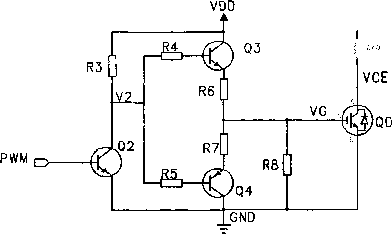
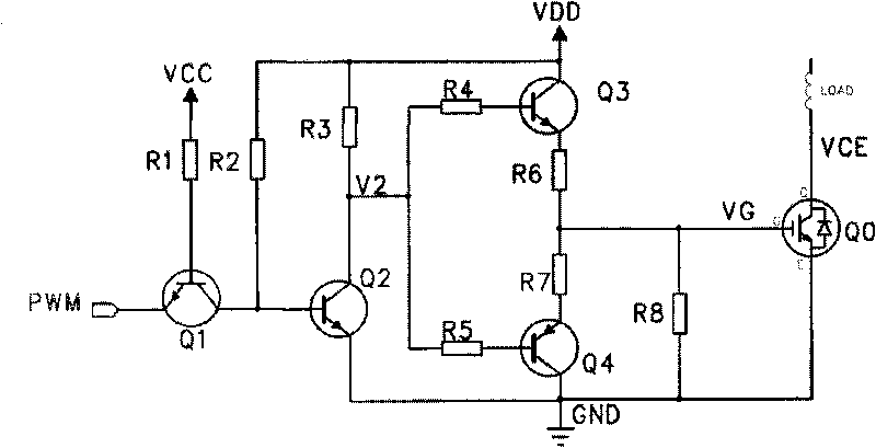
[0020] Embodiment one: if figure 2 As shown, the IGBT drive circuit includes three parts: drive signal amplification, push-pull drive and protection. In the figure, Q0 is an IGBT, which is the target to be driven. Q1, Q2, and Q3 are NPN transistors, and Q4 is a PNP transistor. The PWM signal is connected to the emitter of the transistor Q1, and the base of the transistor Q1 is pulled up to the power supply VCC through the resistor R1; the collector of the transistor Q1 is pulled up to the power supply VDD through the resistor R2, and connected to the base of the transistor Q2; the transistor Q2 is connected to the base of the transistor Q2. Resistor R3 constitutes a typical common-emitter amplifier circuit, which is a preamplifier circuit for PWM signals and has the function of level shifting; transistors Q3 and Q4 are push-pull driven, powered by VDD, and resistors R4 and R5 are respectively connected to transistor Q3 , The base of Q4 limits the current of the base; resist...

Embodiment 2

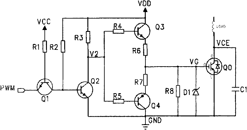
[0024] Embodiment 2: Aiming at the above shortcomings of Embodiment 1, it is improved to Embodiment 2 on the basis of Embodiment 1. Such as image 3 :exist figure 2 On the basis of the first embodiment shown, the voltage regulator D1 is added to be connected in parallel between the gate and the emitter, and the capacitor C1 is added to be connected in parallel between the collector and the emitter of the IGBT. It is also possible to use a scheme in which the diode D1 is separately connected in parallel between the collector and the emitter of the IGBT, or a scheme in which the capacitor C1 is separately connected in parallel between the collector and the emitter of the IGBT; only the corresponding functions are lacking.

[0025] Such as image 3 : Diode D1 is a Zener tube, its voltage regulation value V Z above VDD, below V G the maximum value allowed. If V G A spike that exceeds the gate withstand voltage appears, diode D1 will V G clamped at the regulated value V Z ...


PUM


Abstract

The present invention belongs to the technical field of power electronics, in particular to an IGBT drive and protection circuit which can effectively realize power-down protection and can not be switched on by mistake. The IGBT drive and protection circuit comprises a common-emitter amplifying circuit, and a push-pull drive circuit and IGBT, wherein the common-emitter amplifying circuit is provided with a PWM signal input terminal for amplifying PWM signals, and the push-pull drive circuit is provided with a VDD power supply input terminal for receiving power from a VDD power supply. An NPN triode is connected between the common-emitter amplifying circuit and the PWM signal input terminal. The PWM signal input terminal is led out from the emitter; a base electrode of the terminal is provided with a VCC power supply input terminal through a resistor for receiving power from a VCC power supply; and a collecting electrode of the terminal is connected with the VDD power supply input terminal through a resistor. The IGBT drive and protection circuit has functions of power-down protection, gate protection and overvoltage protection for collecting electrodes, and is stable and reliable.

Description

technical field [0001] The invention belongs to the technical field of power electronics and relates to a driving and protection circuit of an insulated gate bipolar transistor IGBT. Background technique [0002] Insulated gate bipolar transistor IGBT combines the advantages of power transistor and power field effect transistor MOSFET. It has the characteristics of easy driving, large peak current capacity, self-shutoff, and high switching frequency (10-50kHz). It is widely used in small volume, Among high-efficiency variable frequency power supplies, motor speed control, UPS and inverter welding machines, the driving and protection of IGBTs are the key technologies in their applications. [0003] The general IGBT driving circuit in the prior art such as figure 1 , It is not perfect in power-down protection; when the PWM signal terminal loses power, the IGBT will be turned on by mistake; and it lacks gate protection and collector overvoltage protection. Contents of the in...

Claims


Application Information

Patent Timeline
IPC IPC(8): H03K17/08H03K17/567
Inventor 张和君刘远进牛涛
Owner 宁波德业变频技术有限公司
Why Eureka
Try Eureka