
Bidirectional thyristor trigger circuit and method

A bidirectional thyristor and trigger circuit technology, applied in electrical components, output power conversion devices, etc., can solve the problems of low conversion accuracy, scattered device parameters, poor trigger stability, etc., to achieve simple principles, low circuit power consumption, and work. stable effect

Inactive Publication Date: 2013-09-18
HUNAN UNIV OF TECH
View PDF3 Cites 16 Cited by
  • Summary
  • Abstract
  • Description
  • Claims
  • Application Information

AI Technical Summary

Problems solved by technology

[0002] The device parameters in traditional analog flip-flops are relatively scattered, inconvenient to debug and use, poor reliability, high power consumption, and high price; using analog signals for phase shift control, the control signal transmission has poor anti-interference ability
[0003] The traditional digital trigger uses a microcontroller as the control core, which has strong functions, but its price is high, and it is easy to cause the program to run out of control when encountering strong interference
[0004] The patent application number is CN201010529936.5 "a bidirectional thyristor trigger circuit and method", using PWM as the input phase-shift control signal, the circuit is simple and the cost is low, but the PWM signal needs to be converted into a DC voltage through a filter circuit, and the conversion accuracy is not high , and the circuit uses a trigger diode as a trigger comparison device, the minimum phase shift angle is not easy to control when the phase shift angle is small, and the trigger stability is poor when the phase shift angle is large

Method used


Image

  • Bidirectional thyristor trigger circuit and method
  • Bidirectional thyristor trigger circuit and method

Examples


Embodiment Construction

[0038] The present invention will be further described in detail below in conjunction with the embodiments and the accompanying drawings, but the embodiments of the present invention are not limited thereto.

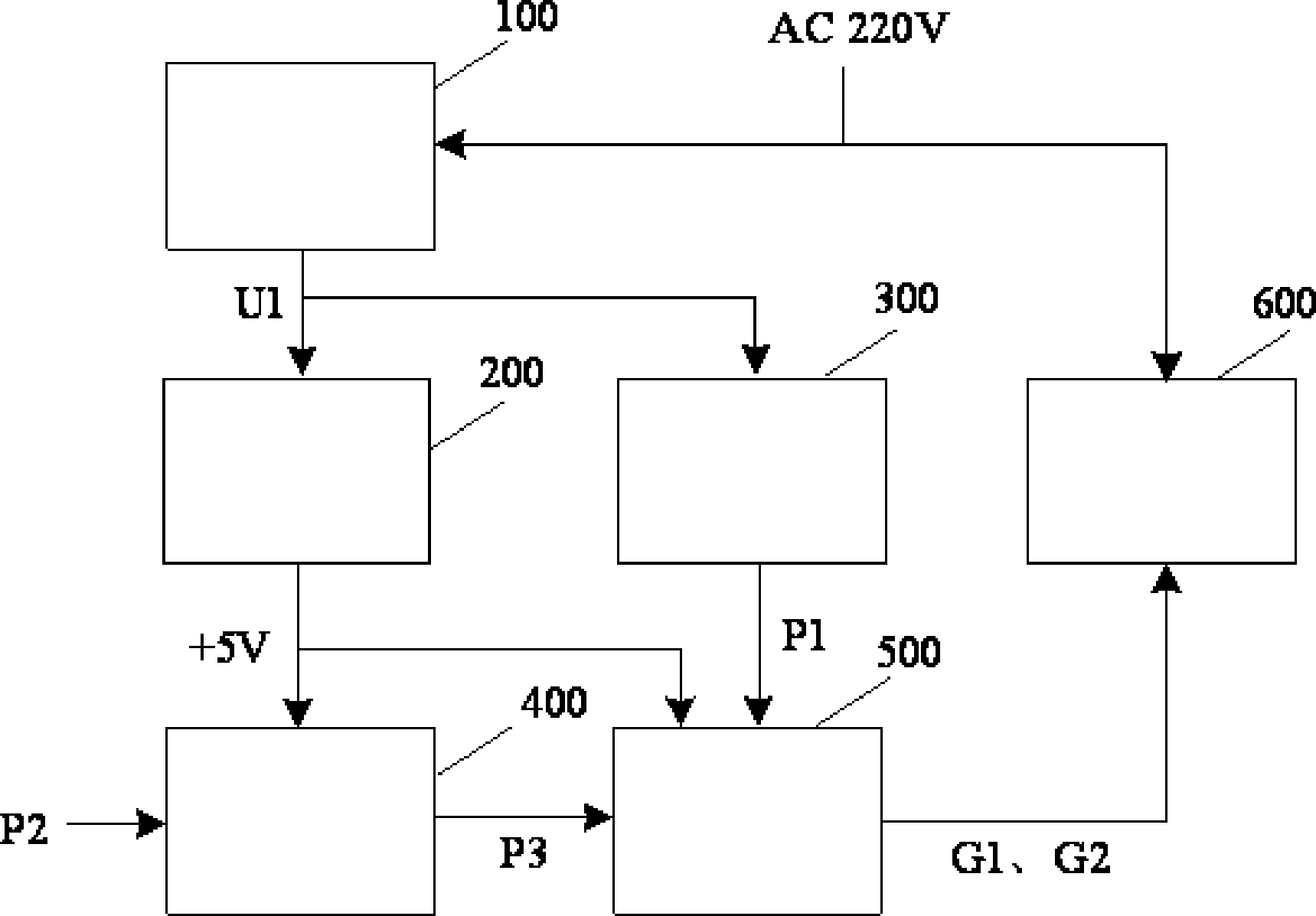
[0039] like figure 1 Shown is a structural block diagram of an embodiment of a bidirectional thyristor trigger circuit, which consists of a full-wave rectifier unit 100, a DC stabilized power supply unit 200, a zero-crossing synchronous pulse generation unit 300, an input signal photoelectric isolation unit 400, a phase-shift trigger unit 500, a bidirectional The thyristor main circuit unit 600 is composed.

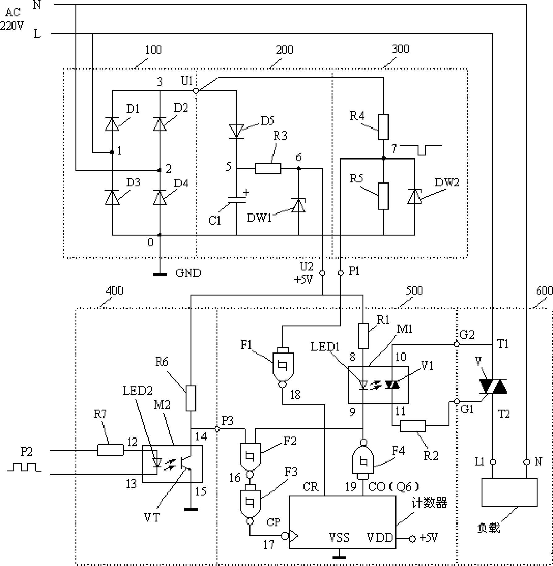
[0040] like figure 2 Shown is a circuit diagram of a circuit embodiment of the present invention.

[0041] The full-wave rectification unit 100 is provided with a first AC input terminal 1, a second AC input terminal 2, a full-wave DC voltage output terminal U1, and a rectified voltage negative output terminal 0; the rectified voltage negative output terminal 0 i...


PUM


Abstract

The invention provides bidirectional thyristor trigger circuit and method. The circuit comprises a full-wave rectifier unit, a direct-current voltage-stabilized power unit, a zero-crossing synch pulse generation unit, an input signal photoelectric isolation unit, a phase shift trigger unit, and a bidirectional thyristor master circuit unit. According to the method, phase shifting is achieved by directly counting of input phase shift control frequency signals with a counter, and phase can be shifted by changing the input phase shift control frequency signals; the phase shift control signals input to the counter are subjected to photoelectric isolation and Schmitt rectification. The circuit is low in cost, small in size, stable and reliable in operation, and applicable as alternating-current voltage regulating switches in automatic control systems.

Description

technical field [0001] The invention belongs to the technical field of thyristor trigger circuits, and in particular relates to a bidirectional thyristor trigger circuit and a method. Background technique [0002] The device parameters in traditional analog flip-flops are relatively scattered, inconvenient to debug and use, poor reliability, high power consumption, and high price; using analog signals for phase-shift control, the control signal transmission has poor anti-interference ability. [0003] The traditional digital trigger uses a microcontroller as the control core, which has strong functions, but its price is high, and it is easy to cause the program to run out of control when encountering strong interference. [0004] The patent application number is CN201010529936.5 "a bidirectional thyristor trigger circuit and method", using PWM as the input phase-shift control signal, the circuit is simple and the cost is low, but the PWM signal needs to be converted into a D...

Claims


Application Information

Patent Timeline
Patent Type & Authority Applications(China)
IPC IPC(8): H02M1/06
Inventor 凌云郭艳杰陈欢李飞
Owner HUNAN UNIV OF TECH
Learn More