
Pre-amplifier and signal acquisition device

A preamplifier and weak signal technology, applied in differential amplifiers, DC-coupled DC amplifiers, positive feedback circuit devices, etc., can solve the problem of common-mode rejection ratio drop, low power consumption and large resistance value, affecting common-mode rejection ratio, etc. question

Active Publication Date: 2016-02-10
SHENZHEN INST OF ADVANCED TECH
View PDF2 Cites 14 Cited by
  • Summary
  • Abstract
  • Description
  • Claims
  • Application Information

AI Technical Summary

Problems solved by technology

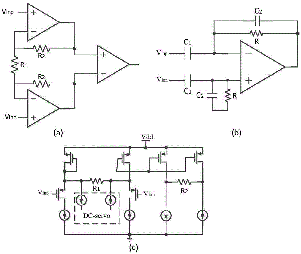
The first is as figure 1 The classic three-op-amp configuration shown in (a) enables high input impedance, but the common-mode rejection ratio (CMRR) suffers from resistor mismatch
In addition, in order to ensure low noise, an amplifier with high power consumption is required; and low power consumption requires a large resistor, which increases the chip area
The second is as figure 1 In the AC coupling-capacitor negative feedback structure shown in (b), the high-pass filter composed of resistors and capacitors can completely eliminate the electrode offset voltage, but the common-mode rejection ratio will decrease due to the mismatch of the feedback capacitor caused by the manufacturing process, and it will increase more chip area
The third is figure 1 (c) The current feedback structure shown in (c) usually requires an external loop to form a high-pass filter to eliminate the electrode offset voltage. However, this loop has certain limitations on the range of offset voltage elimination. The differential input stage caused by the offset voltage Operating Point Mismatch Affects Common Mode Rejection Ratio
In addition, the power consumption of this structure cannot meet the requirements of low power consumption. Low power consumption and high gain require large resistance values, which will occupy too much chip area.

Method used

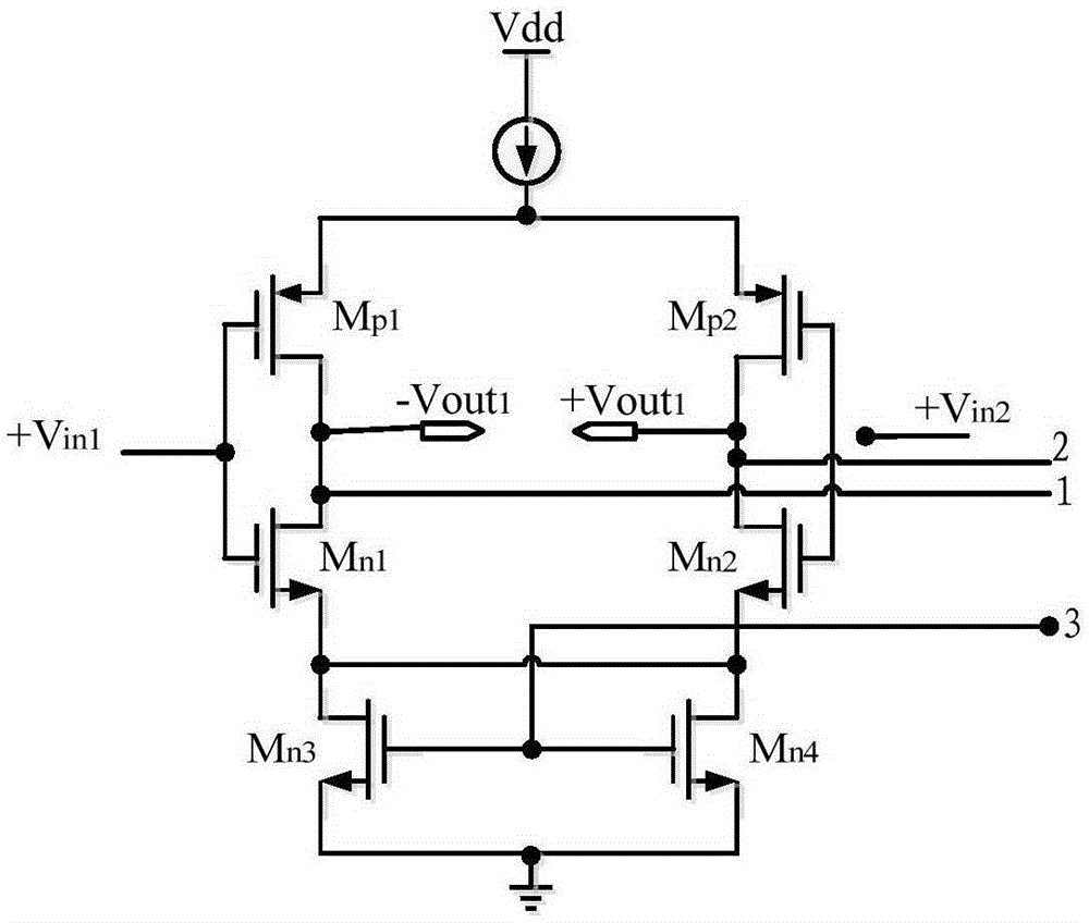

Image

  • Pre-amplifier and signal acquisition device
  • Pre-amplifier and signal acquisition device
  • Pre-amplifier and signal acquisition device

Examples


Embodiment Construction

[0047] In order to make the object, technical solution and advantages of the present invention clearer, the present invention will be further described in detail below in conjunction with the accompanying drawings and embodiments. It should be understood that the specific embodiments described here are only used to explain the present invention, not to limit the present invention.

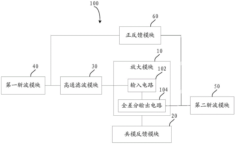
[0048] Such as figure 2 As shown, in some embodiments of the present invention, a preamplifier 100 is provided, and the preamplifier 100 is set in a signal acquisition device for amplifying the collected weak signal. Weak signals mainly refer to signals with low message intensity such as acoustic signals, optical signals or electrical signals, which are small and weak, and are not easily received, felt or received by equipment. Weak signals refer to extremely weak useful signals buried deep in the background noise. With the continuous development of science and technology, the detection of vario...


PUM


Abstract

The invention relates to a pre-amplifier and a signal acquisition device. The pre-amplifier is used for amplifying acquired weak signals and comprises an amplifying module and a common-mode feedback module. The amplifying module comprises an input circuit and a fully-differential output circuit. The output end of the input circuit is connected with the input end of the fully-differential output circuit. The fully-differential output circuit is provided with two differential mode output ends. The amplifying module is used for amplifying an input signal and acquiring an output signal. The common-mode feedback module comprises a common-mode feedback circuit and a common-mode feedback circuit of a source electrode degradation structure. The common-mode feedback module is connected with the amplifying module and used for suppressing common-mode gains of the output signal. The pre-amplifier and the signal acquisition device can reduce the size of a chip and reduce influences of capacitance matching on the common-mode rejection ratio.

Description

technical field [0001] The invention relates to the technical field of integrated circuits, in particular to a preamplifier and a signal acquisition device. Background technique [0002] As a key component of the acquisition chip of physiological signals such as ECG signals, the preamplifier or instrumentation amplifier (IA) of the analog front-end circuit determines the quality of physiological signal acquisition. [0003] At present, the existing IA mainly has three structures. The first is as figure 1 The classic three-op-amp configuration shown in (a) enables high input impedance, but the common-mode rejection ratio (CMRR) suffers from resistor mismatch. In addition, in order to ensure low noise, an amplifier with high power consumption is required; and the consumption of low power consumption requires a large resistor, which increases the chip area. The second is as figure 1 In the AC coupling-capacitor negative feedback structure shown in (b), the high-pass filter ...

Claims


Application Information

Patent Timeline
IPC IPC(8): H03F1/38H03F3/45
Inventor 张浩李烨
Owner SHENZHEN INST OF ADVANCED TECH
Learn More