Permanent-magnet rotor and rotating machine comprising such a rotor

A permanent magnet, rotating technology, used in synchronous motors with static armatures and rotating magnets, magnetic circuit rotating parts, manufacturing stator/rotor bodies, etc., can solve problems such as reducing rotor performance

Inactive Publication Date: 2012-12-05
MOTEURS LEROY SOMER
View PDF13 Cites 16 Cited by
  • Summary
  • Abstract
  • Description
  • Claims
  • Application Information

AI Technical Summary

Problems solved by technology

Improper positioning of these magnets often results in unwanted air gaps that degrade the performance of the rotor and force it to be adjusted very finely

Method used


Image

  • Permanent-magnet rotor and rotating machine comprising such a rotor
  • Permanent-magnet rotor and rotating machine comprising such a rotor
  • Permanent-magnet rotor and rotating machine comprising such a rotor

Examples


Embodiment Construction

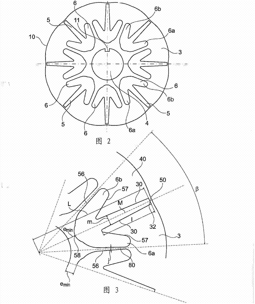
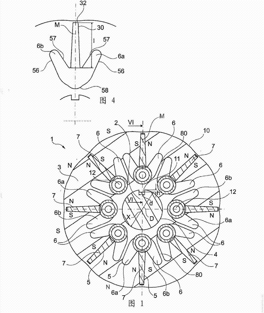
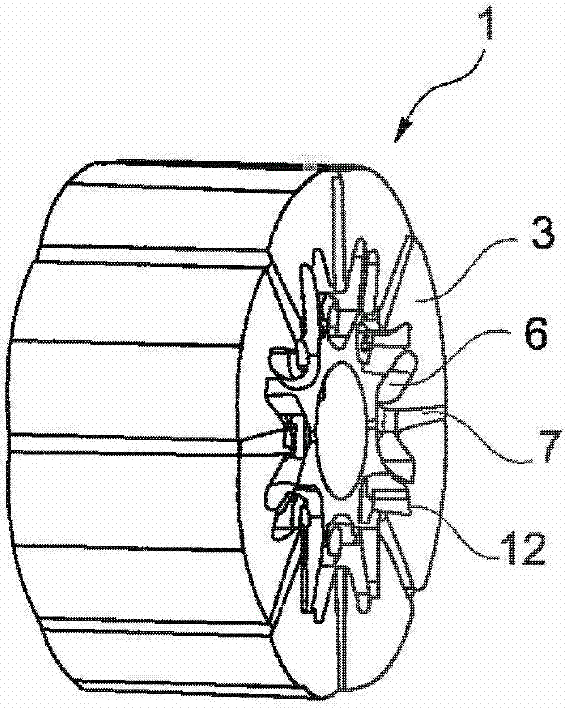
[0116] figure 1 The device 1 depicted in includes a magnet frame 3 extending radially along the axis of rotation X of the rotor, which frame is preferably formed of stacks of laminations stacked along the axis X, the laminations being considered in this example as complete identical and exactly overlapping.

[0117] The rotor 1 comprises a plurality of permanent magnets 7 placed in respective accommodation areas 5 of the magnetic rotor frame 3 so that two consecutive magnets 7 have the same polarity on faces facing each other.

[0118] The rotor frame 3 is mounted on a support body 2 , which is, in the example considered, a shaft made of a magnetic material such as steel.

[0119] The rotor frame 3 has a central opening 4 for mounting it on the shaft 2 . D The central opening 4 has a diameter D of, for example, between 40 mm and 50 mm.

[0120] Furthermore, the central opening 4 has an anti-rotation projection 11 which engages in a corresponding slot in the shaft.

[0121]...


PUM


Abstract

The invention relates to a rotor (1) of a rotating electric machine, having permanent magnets (7) and flux concentration. The rotor comprises a rotor casing (3) having radially oriented housings (5) in which the permanent magnets (7) are disposed. The width of each housing (5) over at least one portion that is in contact with the magnet (7) decreases extending away from the axis of the rotor (1). Moreover, each housing (5) opens at its radially inner end into a hole (6) extending from both sides of a midplane (M) of the housing (5).

Description

technical field [0001] This invention relates to rotary electric machines, notably synchronous electric machines, and more particularly to machines including flux-concentrating permanent magnet rotors. Background technique [0002] A flux-concentrating rotor consists of a rotor frame, also referred to as a rotor body, which houses a plurality of magnets, which are mounted in radially directed containment areas. [0003] Several types of flux concentrating rotors are known. [0004] It is worth noting that there are known rotors which comprise a non-magnetic central piece to which pole pieces are attached and between which permanent magnets are interposed, as described for example in application EP 1 152 516 . [0005] Patent application DE 10 2009 026 524 relates to an electric machine having a rotor comprising pole pieces and connecting bridges connected by fixed collars. The bridges define a plurality of grooves and receiving areas for receiving a plurality of magnetic p...

Claims


Application Information

Patent Timeline
Patent Type & Authority Applications(China)
IPC IPC(8): H02K1/27H02K1/28H02K15/03H02K21/12
CPCH02K1/2773H02K1/28
Inventor 帕斯卡尔・贝诺帕斯卡尔・戈捷克里斯托夫・吉勒斯雅克・圣-米歇尔奥利维耶・萨维努瓦
Owner MOTEURS LEROY SOMER
Why Eureka
Try Eureka