Permanent magnet rotor

a permanent magnet and rotor technology, applied in the direction of dynamo-electric machines, magnetic circuit rotating parts, magnetic circuit shape/form/construction, etc., can solve the problems of difficult insertion of magnets into the rotor cavity and time-consuming

Inactive Publication Date: 2006-05-18
EMERSON ELECTRIC CO
View PDF15 Cites 40 Cited by
  • Summary
  • Abstract
  • Description
  • Claims
  • Application Information

AI Technical Summary

Benefits of technology

[0005] The inventor of the present invention has succeeded at designing a rotor for electric machines (such as electric motors, generators, and other dynamoelectric machines). The rotor has cavities with block

Problems solved by technology

As the rotor core is formed from magnetically conducting material, the insertio

Method used


Image

  • Permanent magnet rotor
  • Permanent magnet rotor
  • Permanent magnet rotor

Examples


Embodiment Construction

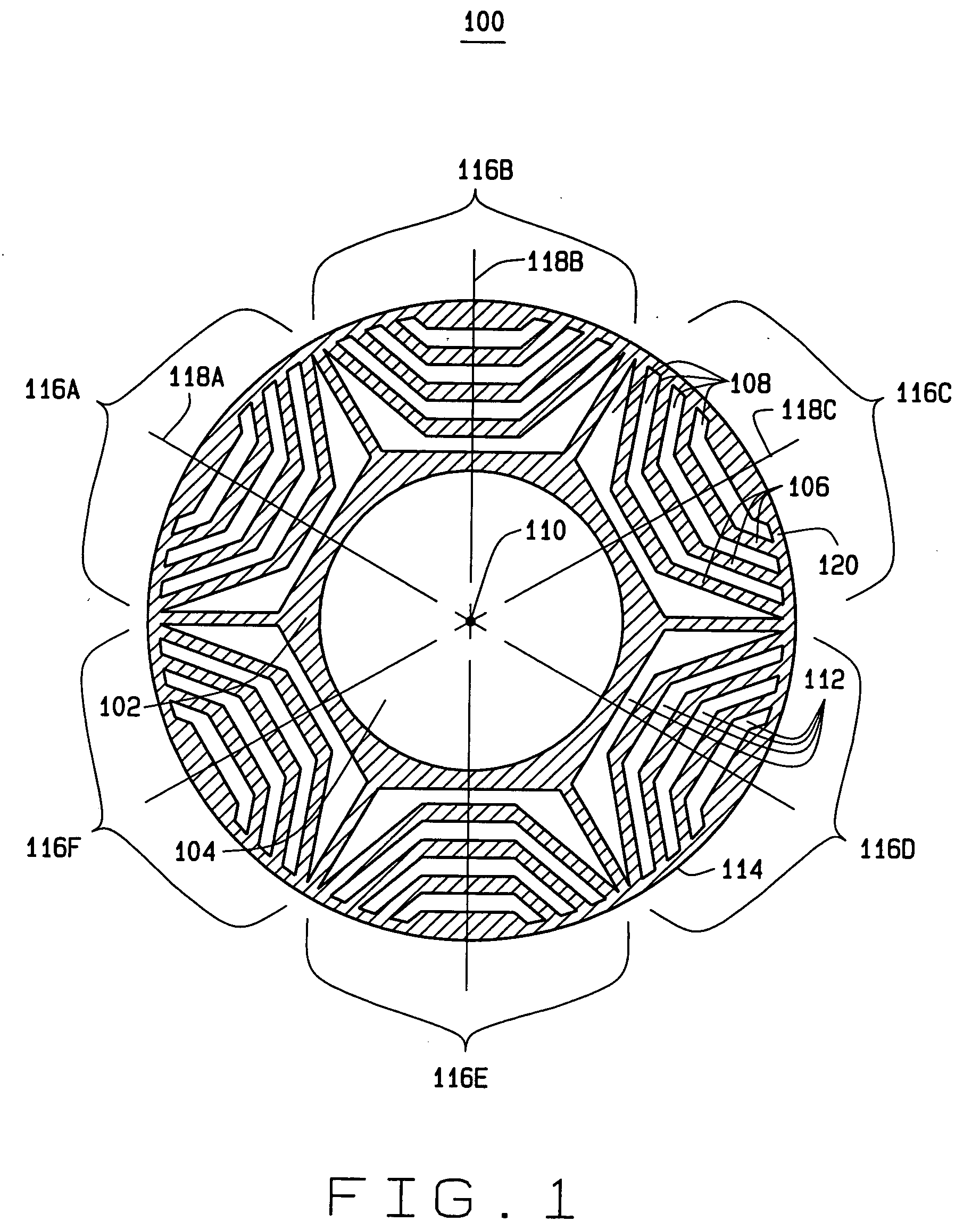
[0025] A core of a rotor for an electric machine is illustrated in FIG. 1 according to one exemplary embodiment of the invention. A rotor core 100 includes a core body 102 composed of a magnetically conductive material. The rotor core body 102 can be a single or monolithic body having a length defining a rotor length or can be a plurality of plates of conductive material that are laminated together to define the length of the rotor.

[0026] The rotor core body 102 has a center arbor 104 or cavity about a center axis 110 and a perimeter 114. The center arbor 104 provides for insertion of a shaft (not shown) or arbor for attachment to a shaft. In other embodiments, the center arbor 104 can be a shaft hole dimensioned for insertion of an electric machine shaft. The rotor core body 102 includes a plurality of cavities 108 and flux channels 106 formed by the rotor core body 102. The flux channels 106 separate the plurality of cavities 108 and define each of the plurality of rotor poles 11...


PUM


Abstract

A rotor for an electric machine has a rotor core with a plurality poles and a method of magnetizing the poles of a rotor. At least one of the poles includes a plurality of cavities spaced radially from one another with each of the cavities having a magnet portion. Each of a plurality of block magnets has substantially the same width and is positioned within one of the magnet portions of the cavities.

Description

FIELD OF THE INVENTION [0001] The present invention relates to an electric machine and more specifically relates to a rotor for an electric machine having permanent magnets. BACKGROUND OF THE INVENTION [0002] A wide variety of electric machines are known in which a plurality of magnets are positioned on or within a core to form a rotor for an electric machine such as an electric motor, electric generator, or dynamoelectric machine. The rotor core can be formed from a solid magnetically conductive material or can be formed from a plurality of plates of magnetically conducting material laminated to form a particular rotor stack height. [0003] Various techniques are known for positioning the magnets on or within the core. Magnets are positioned on or within the body of the rotor to define a plurality of alternating North and South magnetized or biased rotor poles. Typically, cavities are created in the rotor core body to define each of the rotor poles. Each pole is can be defined by on...

Claims


Application Information

Patent Timeline
IPC IPC(8): H02K21/12H02K1/27
CPCH02K1/276H02K21/16
Inventor HORST, GARY E.
Owner EMERSON ELECTRIC CO
Why Eureka
Try Eureka