Blade driving apparatus for cameras

a driving apparatus and camera technology, applied in the direction of optics, shutters, instruments, etc., can solve the problems of not necessarily being favorable, above problems becoming severe, etc., and achieve the effects of convenient assembly work, slim apparatus design, and convenient assembly work

Active Publication Date: 2007-08-30
COPAL CO LTD
View PDF10 Cites 38 Cited by
  • Summary
  • Abstract
  • Description
  • Claims
  • Application Information

AI Technical Summary

Benefits of technology

[0015]In this case, when the apparatus is constructed so that at least one of the shanks of the two rotors is constructed so that its top is introduced into the blade chamber, and is also used as one of the shanks for the two blades, the design where a plurality of blades are provided is facilitated to offer an advantage to compactness of the apparatus. In addition, when the apparatus is constructed so that at least one of the two bobbins is molded integrally with the cover frame or at least one of the two cover frames has a notch and a part of one of the two bobbins and a part of the coil wound around this bobbin are placed in the notch, this is advantageous for the slim design of the apparatus. The blade driving apparatus for cameras of the present invention, in which the compact and slim design is possible, is favorably applied to a camera incorporated in each of various installations as the apparatus controlling the amount of light of a solid-state image sensor. Therefore, the information terminal, such as the mobile phone or PDA, and the in-vehicle camera, incorporating the apparatus, come into the category of the present invention.
[0016]In the blade driving apparatus for cameras of the present invention, the permanent magnet rotor, the partition plate, and the blades, after being assembled in turn with respect to the shanks set upright on the cover frame, can be mounted to the base plate, and thus assembly work is favorably performed. Furthermore, since the permanent magnet rotor is supported by the cover frame and the thin partition plate, the number of degrees of design freedom is increased with respect to the mounting position and shape of the blade even when the base plate is reduced in size. When it is desired that the number of blades is increased and the base plate is reduced, this is particularly advantageous.

Problems solved by technology

However, this arrangement, although favorable for the slim design of the apparatus, is not necessarily be favorable in the case where the area of the base plate (the base plate 1) is reduced to achieve compactness of the apparatus.
In particular, when three or more blades are used and an attempt is made to further reduce the housing area of the blades in a fully opened state, the above problem becomes severe.

Method used


Image

  • Blade driving apparatus for cameras
  • Blade driving apparatus for cameras
  • Blade driving apparatus for cameras

Examples


embodiment 1

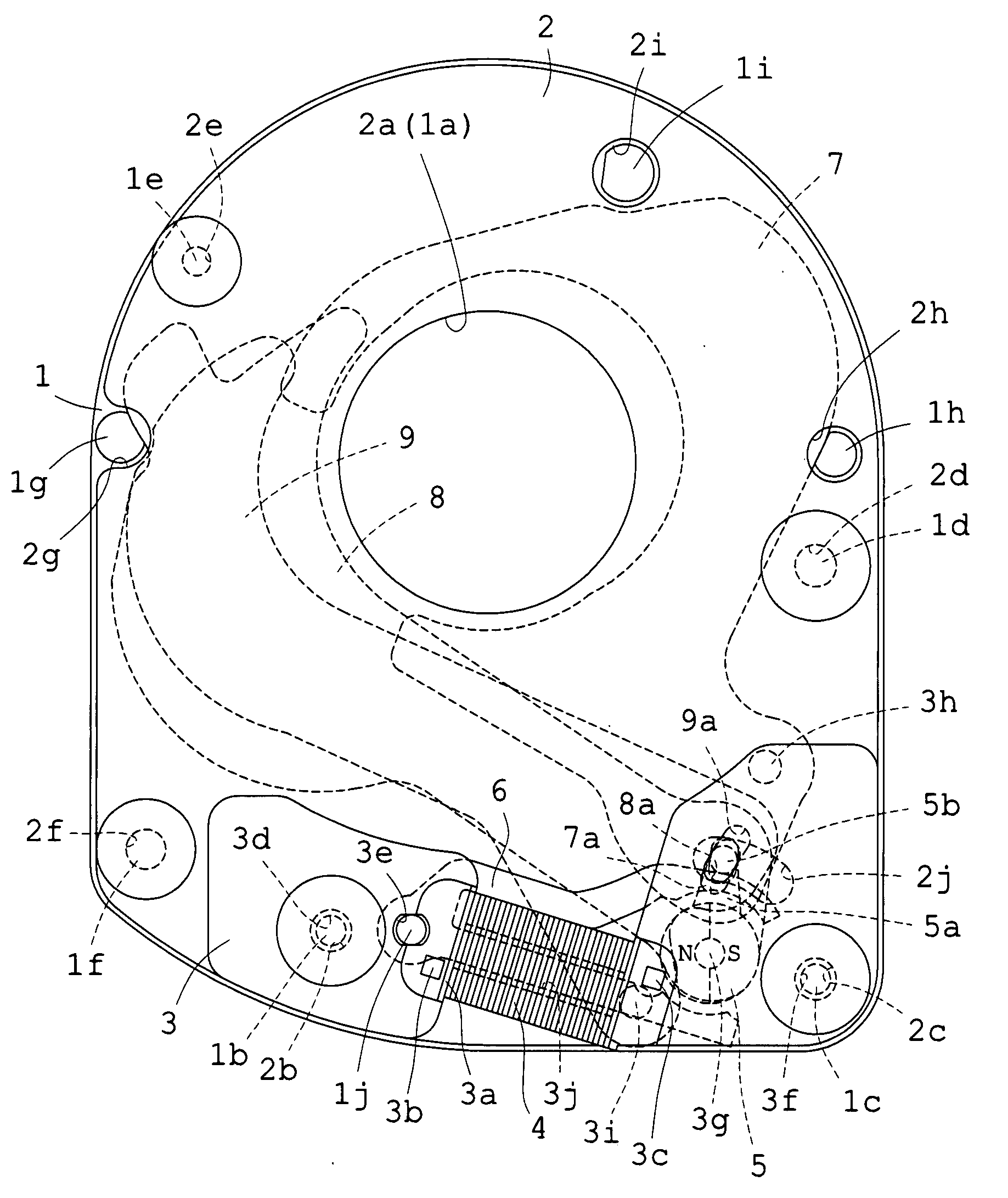
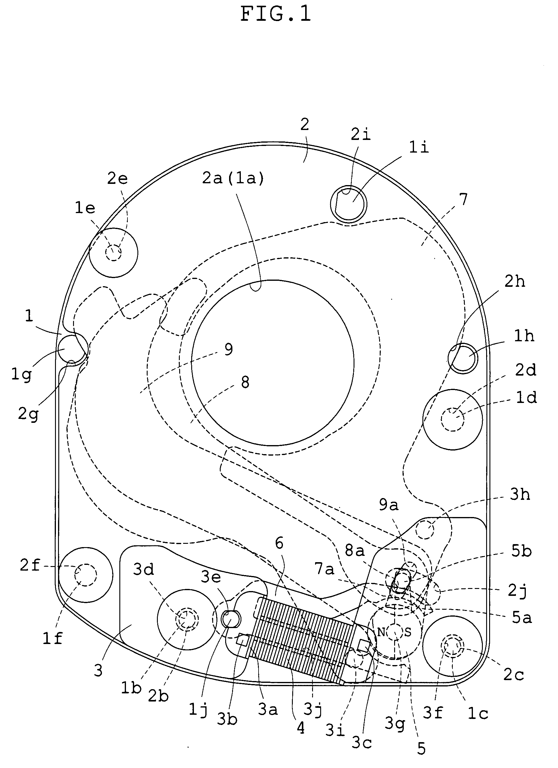
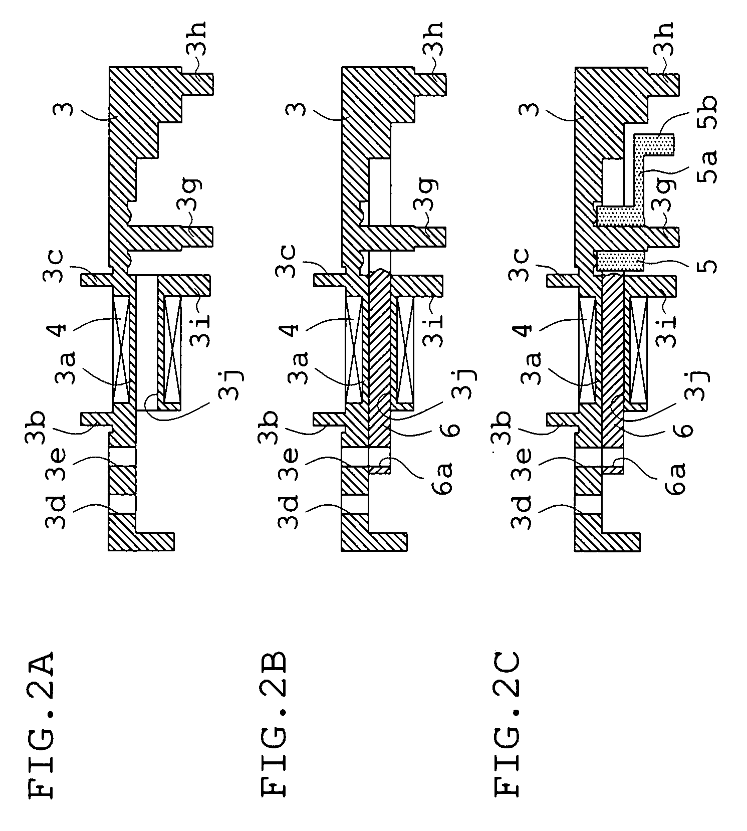
[0030]With reference to FIGS. 1 to 5A-5C, Embodiment 1 will be described. The structure of this embodiment is first explained, mainly using FIGS. 1 and 3A-3C. A base plate 1 of the embodiment, made of synthetic resin, is a relatively thick member and has a circular aperture section 1a for a photographing optical path. In the base plate 1, five mounting shanks 1b, 1c, 1d, 1e, and 1f, three stopper pins 1g, 1h, and 1i, and a positioning pin 1j are set upright on one surface by integral molding, and as shown in FIG. 3C, a non-through slot 1k and three non-through holes 1m, 1n, and 1p are provided. At the position where the positioning pin 1j is set upright, a large thickness portion 1q (see FIG. 3C) is configured. In contrast to this, a remaining surface has a flat shape free from projections.

[0031]A partition plate 2 is configured into an extremely thin plate shape so that a blade chamber is provided between the base plate 1 and the partition plate 2, and has a circular aperture secti...

embodiment 2

[0052]Subsequently, Embodiment 2 will be described in reference to FIGS. 7-11. In this embodiment, the shutter apparatus and the stop apparatus are constructed as one unit. The structure of the shutter apparatus is substantially the same as in Embodiment 1. Like reference numerals are thus used for the members of the shutter apparatus with respect to Embodiment 1, and their detailed description is omitted. However, the base plate and the partition plate of the embodiment are different from those of Embodiment 1. Hence, the description of the structure of the embodiment is mainly given of the base plate, the partition plate, and the stop apparatus.

[0053]A base plate 11 of the embodiment is made of synthetic resin and is provided with a circular aperture section 11a for a photographing optical path. In this base plate 11, six mounting shanks 11b, 11c, 11d, 11e, 11f, and 11g; five stopper pins 11h, 11i, 11j, 11k, and 11m; and two positioning pins 11n and 11p are set upright by integral...


PUM


Abstract

A blade driving apparatus for cameras includes a base plate having an aperture section for a photographing optical path; a partition plate having an aperture section for the photographing optical path so that a blade chamber is interposed between the base plate and the partition plate; a cover frame having an actuator chamber between the partition plate and the cover frame; a permanent magnet rotor rotatably mounted on the cover frame so that an output pin is introduced into the blade chamber; a yoke in which tops of two legs constructed as magnetic pole sections are opposite to the peripheral surface of the rotor in the actuator chamber and one of the two legs is fitted into a bobbin around which a coil is wound; and at least one blade rotatably mounted to a shank for at least one blade which is set upright on the cover frame and is introduced into the blade chamber, and introduced into, and removed from, the exposure aperture by the output pin.

Description

BACKGROUND OF THE INVENTION[0001]1. Field of the Invention[0002]This invention relates to a blade driving apparatus for cameras designed so that blades, such as shutter blades or stop blades, are driven by an electromagnetic actuator.[0003]2. Description of Related Art[0004]Each of lens shutter apparatuses (hereinafter referred to as shutter apparatuses), stop apparatuses, filter apparatuses, and lens barrier apparatuses which are used in recent cameras has a single blade or a plurality of blades so that they are reciprocated by an electromagnetic actuator. As is well known, each of these apparatuses may be unified by itself, but two or three of them may be constructed as one unit.[0005]The shutter apparatuses are generally designed so that two shutter blades are reciprocated and rotated simultaneously in opposite directions. However, some of the shutter apparatuses may be constructed so that a single shutter blade is reciprocated and rotated. It is also known that at least one of t...

Claims


Application Information

Patent Timeline
Patent Type & Authority Applications(United States)
IPC IPC(8): G03B9/08
CPCG03B9/18G03B9/08G03B9/10
Inventor KIHARA, TOMOKAZU
Owner COPAL CO LTD
Why Eureka
Try Eureka