
filter device

A filtration device and fiber filtration technology, applied in the direction of filtration separation, gravity filter, loose filter material filter, etc., can solve the problems of difficult to press evenly, create gaps in the boundary, damage the filtration function, etc., and achieve the filtration operation. Excellent efficiency

Active Publication Date: 2016-12-14
トーケミ
View PDF5 Cites 0 Cited by
  • Summary
  • Abstract
  • Description
  • Claims
  • Application Information

AI Technical Summary

Problems solved by technology

[0005] In the above-mentioned existing examples, in the former structure, the large impurities are captured by the floating filter member, and the small impurities are captured by the fiber filter member to improve the filtration efficiency. structure, so not only is it difficult to make the compacted state formed by the flow of raw water uniform, but also sometimes voids are created through which raw water flows as a short circuit flow, thereby impairing the filtration function
[0006] In addition, in the latter structure, since the upper and lower ends of the fiber filter member are fixed, the positional relationship of each filter member formed by the flow of raw water is relatively stable, and it becomes a uniformly compacted state. When changing to high speed or due to the change in the filling method of the filter elements in the filter chamber, sometimes gaps are created between the filter elements or at the boundary between the filter elements and the side walls of the filter chamber
In addition, in the latter structure, since the impurity trapping member protrudes from the outer peripheral side of the core material to form a fiber filter member, the part of the trapping member that is away from the periphery of the core portion is empty than the periphery of the core portion, and the raw water passes through. The above-mentioned gaps and empty parts flow and short-circuit, reducing the filtering function

Method used


Image

  • filter device
  • filter device

Examples


Embodiment Construction

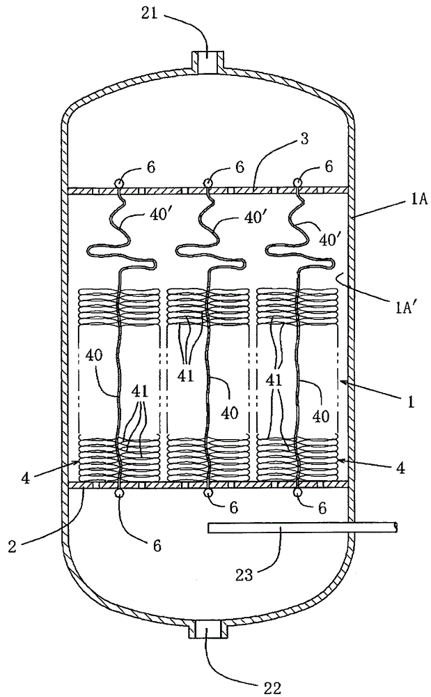
[0014] Accompanying drawing represents an embodiment of the filtering device of the present invention, and in the figure, 1 is filter chamber, and filter chamber 1 is that the inner wall 1A ' of filter bag 1A, perforated plate 2 and upper side perforated plate 3 are carried out to described filter tank 1A. Divided, the porous plate 2 is arranged in the filter tank 1A and constitutes a filter member support plate, and the upper porous plate 3 is arranged in the filter tank 1A opposite to the porous plate 2 . In addition, the filter tank 1A has an inlet for raw water (also used as an outlet for cleaning water and air) 21 on the upstream side, and an outlet for filtered water (also used as an outlet for cleaning water) 22 and a downstream side. Injection ports 23 for cleaning air are communicated with the filter chamber 1 (known).

[0015] An appropriate number of fibrous filter members 4 are accommodated in the filter chamber 1 to perform filtering operations. The fibrous filter...


PUM


Abstract

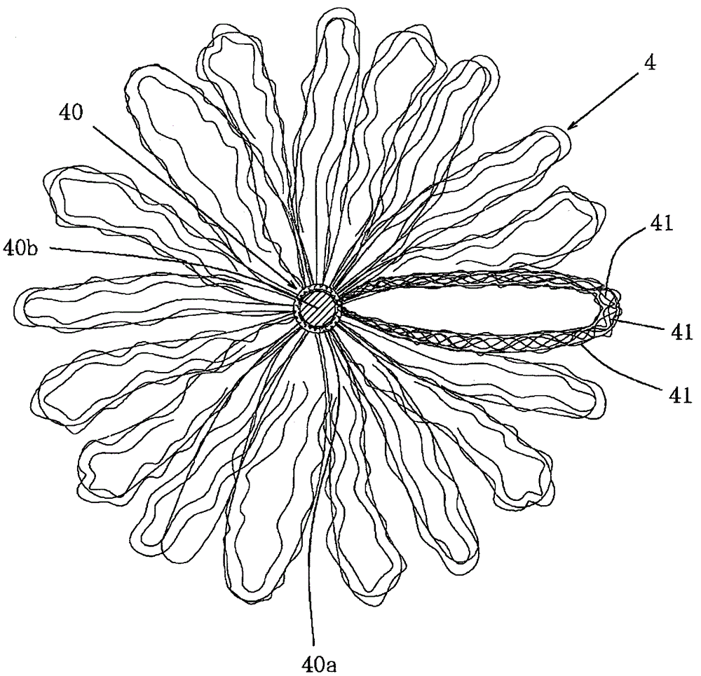
The present invention can prevent the occurrence of short-circuit flow that reduces the filtering function, and provides a filtering device excellent in the filtering function. A filter chamber located between the perforated plate constituting the filter member support plate and the perforated plate on the upstream side facing the perforated plate in the water flow direction of the raw water is filled with an appropriate amount of fiber filter members, one end of which is fixed to the On the porous plate, the other end of the fiber filter member is fixed on the upstream porous plate. In addition, the fiber filter member includes: a cord-shaped core material whose length is longer than the length of the filter chamber in the flow direction of the raw water by a predetermined amount; an innumerable number of resin fibers subjected to a bulking process, and which are obtained from the core material. The outer peripheral side protrudes radially and forms an infinite number of rings. The core material is provided with a predetermined length of a portion in which the resin fiber is not provided, and only the core material is present.

Description

technical field [0001] The present invention relates to filtration devices for capturing impurities from water, waste water, other raw water. Background technique [0002] With regard to the structure in which the filter chamber is filled with a long fiber filter member in the flow direction of raw water to form a filter device, there is a filter member whose lower end is fixed to a perforated plate constituting the filter chamber and a filter member is arranged above the filter member. There is a structure in which the filter member is floating (for example, Patent Document 1), and a structure in which the upper and lower ends of the filter member are fixed to a filter chamber constituting member such as a perforated plate (for example, Patent Document 2). [0003] Patent Document 1: JP Unexamined Publication No. 2003-265907; [0004] Patent Document 2: JP Unexamined Patent Publication No. 2002-45612. [0005] In the above-mentioned existing examples, in the former struct...

Claims


Application Information

Patent Timeline
Patent Type & Authority Patents(China)
IPC IPC(8): B01D24/12
Inventor 细谷卓也
Owner トーケミ
Learn More