Supercharge Your Innovation With Domain-Expert AI Agents!

Camera for terminal equipment and implementation method of camera for terminal equipment

A terminal equipment and camera technology, applied in image communication, color TV parts, TV system parts, etc., can solve problems such as inconvenient use, poor user experience, poor camera effect, etc., to achieve convenient use and realize automatic adjustment , improve the effect of the camera

Active Publication Date: 2015-01-21
GOERTEK OPTICAL TECH CO LTD
View PDF6 Cites 0 Cited by
  • Summary
  • Abstract
  • Description
  • Claims
  • Application Information

AI Technical Summary

Problems solved by technology

[0005] The present invention provides a camera for terminal equipment and a method for realizing the camera for terminal equipment, in order to solve the poor camera effect caused by the fixed camera angle of the existing solution , Inconvenient use and poor user experience

Method used


Image

  • Camera for terminal equipment and implementation method of camera for terminal equipment
  • Camera for terminal equipment and implementation method of camera for terminal equipment
  • Camera for terminal equipment and implementation method of camera for terminal equipment

Examples


Embodiment Construction

[0027] In order to make the objectives, technical solutions, and advantages of the present invention clearer, the embodiments of the present invention will be described in further detail below in conjunction with the accompanying drawings.

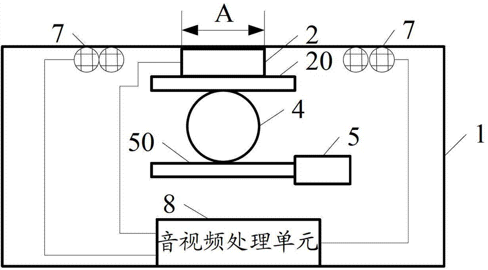
[0028] See figure 1 , Is a camera for terminal equipment provided in the first embodiment of the present invention. The camera includes a housing 1, a lens 2, a lens holder 4, a horizontal motor 5, a microphone array 7 and an audio and video processing unit 8.

[0029] The lens 2, the lens holder 4, and the horizontal motor 5 are contained in the housing 1, and the area of ​​the housing corresponding to the lens (the area marked A in the figure) is a transparent area;

[0030] The horizontal motor 5 is connected to the movable lens holder 4 through the horizontal motor connecting portion 50;

[0031] The lens 2 is connected to the movable lens holder 4 through the lens connecting portion 20.

[0032] The microphone array 7 is electrically connected ...


PUM


Abstract

The invention discloses a camera for terminal equipment and an implementation method of the camera for the terminal equipment. By the camera for the terminal equipment and the implementation method, camera shooting effects can be improved, use is facilitated for users, and user experience is improved. The camera for the terminal equipment comprises a lens, a lens retainer and a horizontal motor, the lens, the lens retainer and the horizontal motor are accommodated in a casing, an area of the casing corresponding to the lens is a transparent area, the horizontal motor is connected to the movable lens retainer through a horizontal motor connecting portion, and the lens is connected to the movable lens retainer through a lens connecting portion. A microphone array is electrically connected with an audio and video processing unit and sends acquired target voice signals to the audio and video processing unit, so that the audio and video processing unit orients a target. The lens is electrically connected with the audio and video processing unit, acquires target images of the oriented target and sends the acquired target images of the oriented target to the audio and video processing unit, so that the audio and video processing unit positions the target.

Description

Technical field [0001] The present invention relates to the technical field of terminal equipment development, in particular to a camera for terminal equipment and a method for implementing the camera for terminal equipment. Background technique [0002] With the rapid development of science and technology, the functions of various terminal devices are becoming more and more powerful. Many terminal devices are equipped with video capture functions. For example, a TV equipped with a camera can use the camera to collect images so that users can use the TV to capture images. Video communication is possible. [0003] However, the current terminal equipment equipped with a camera has at least the following defects: [0004] The camera is fixed on the terminal device, and the lens position of the camera is fixed, which results in a fixed camera angle, poor camera effect, inconvenient use, and poor user experience. Summary of the invention [0005] The present invention provides a camera f...

Claims


Application Information

Patent Timeline
Patent Type & Authority Patents(China)
IPC IPC(8): H04N5/225H04N5/232H04N21/4223
Inventor 胡明辉郎园园毕龙涛于大超
Owner GOERTEK OPTICAL TECH CO LTD
Features
  • R&D
  • Intellectual Property
  • Life Sciences
  • Materials
  • Tech Scout
  • Unparalleled Data Quality
  • Higher Quality Content
  • 60% Fewer Hallucinations
Learn More