Bridge crane

An overhead crane and rope technology, which is applied in the directions of walking overhead cranes, cranes, and trolley cranes, can solve the problems of danger, rope slack, and time-consuming hoisting mechanism, and achieves reduction in size and accurate lifting work. Effect

Active Publication Date: 2012-12-19
KONECRANES GLOBAL
View PDF6 Cites 5 Cited by
  • Summary
  • Abstract
  • Description
  • Claims
  • Application Information

AI Technical Summary

Problems solved by technology

When the load is first secured to the hoist hook during the hoisting phase, it always takes some time for the hoisting mechanism before the slack rope caused by sagging is tensioned
This can be dangerous if not prepared for this, slack in the rope caused by sagging is dangerous in installation work where the crane is used for precision lifting

Method used


Image

  • Bridge crane
  • Bridge crane
  • Bridge crane

Examples


Embodiment Construction

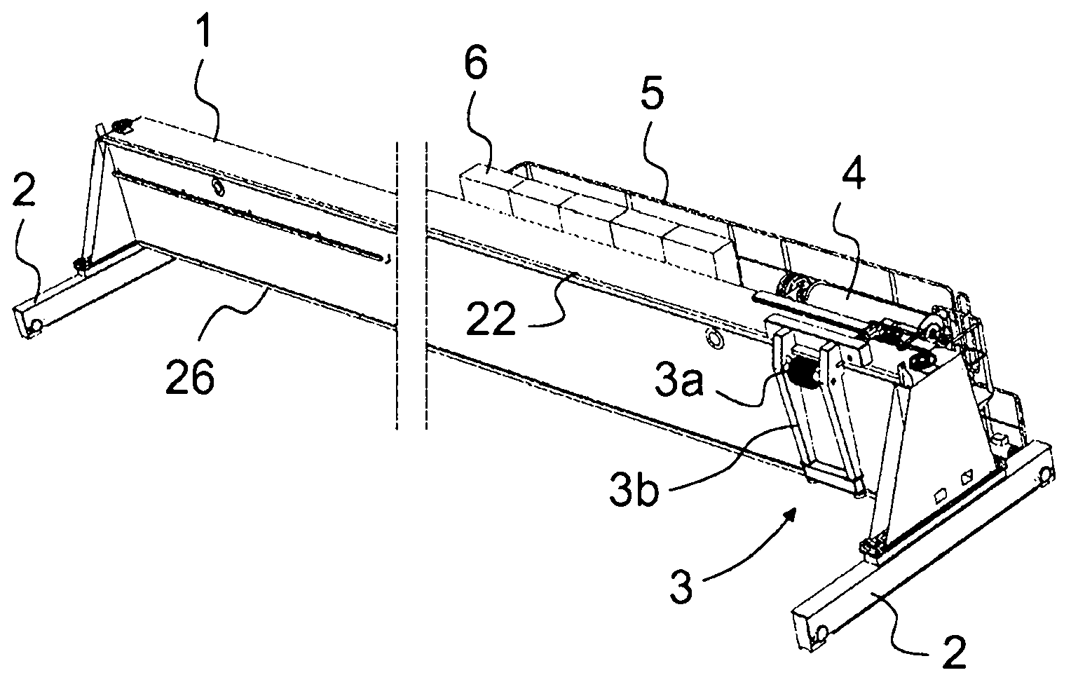
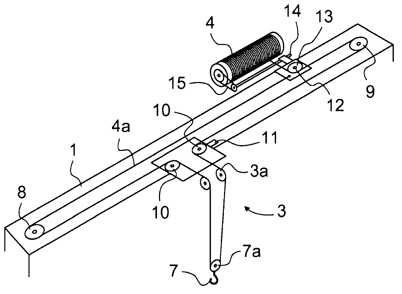
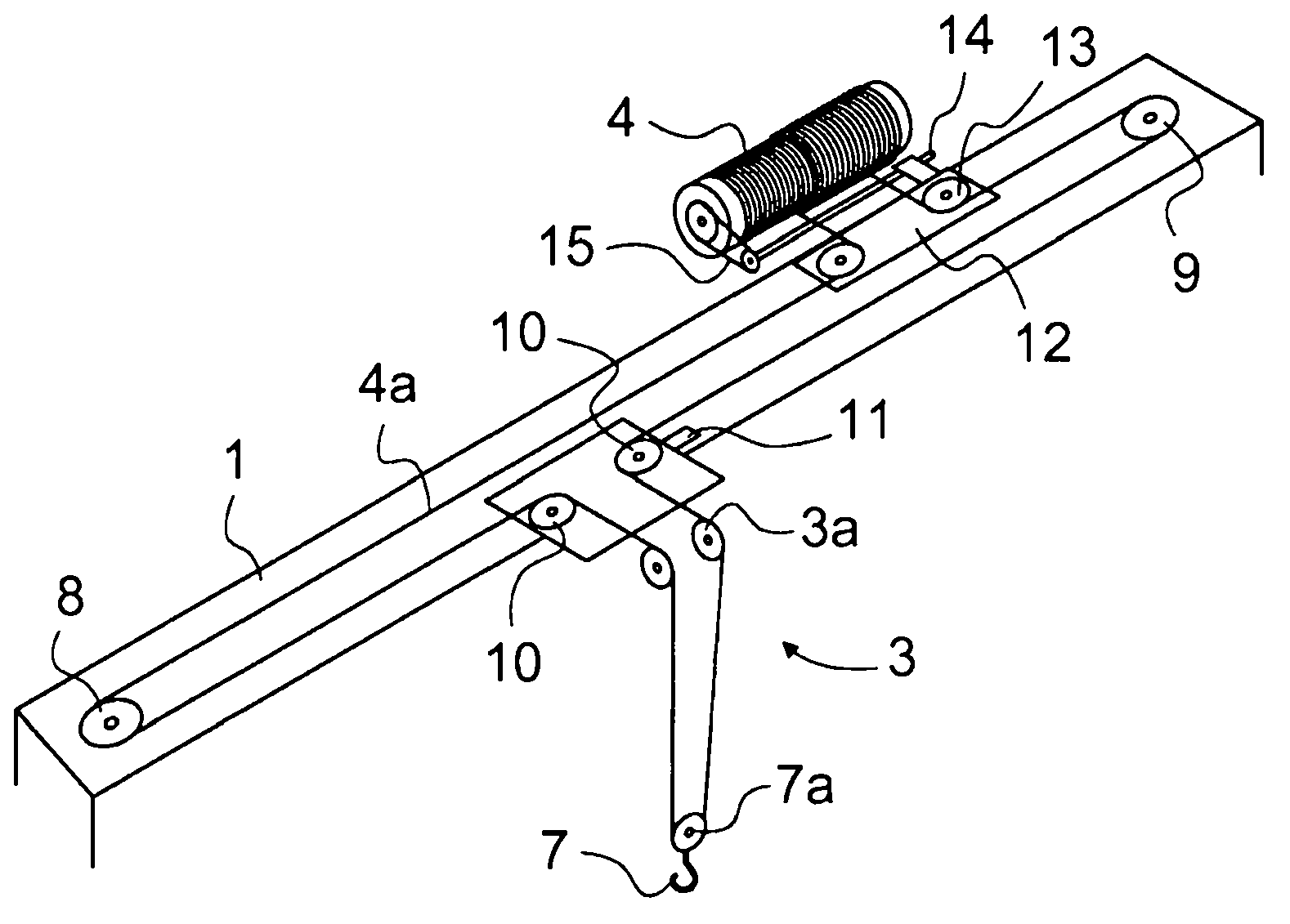
[0014] figure 1 An oblique top view of a simplified and segmented bridge crane according to the invention is shown, without the hoisting rope, the hook and some other parts belonging to the solution, which will be described below. Bridge cranes are also known as torsion bridge cranes and they comprise a main girder 1 at both ends of which are end carriages 2 provided with at least rails Wheels and traveling mechanism. The hoisting block 3 is fitted in conjunction with the first side of the main girder on which the block travels in a lateral direction with respect to the direction of travel of the main girder 1 . The hoisting block 3 comprises a pulley 3a for hoisting the ropes and a frame part provided with legs 3b which rests in the longitudinal direction of the main girder on guide rails 22 and 26 which are at the top of the main girder 1 and on the bottom edge of the first side of the main girder 1. to combine Figure 7 The structure of the guide rail and hoisting block...


PUM


Abstract

The object of the invention is a bridge crane, which comprises a main girder (1), which is fitted to travel supported by end carriages (2) essentially at both ends and which bridge crane further comprises a hoisting trolley (3) traveling supported by the main girder (1) and a rope drum (4) mounted on bearings to rotate in an essentially stationary position, from which rope drum the hoisting rope (4a) is guided to a hook (7) traveling along with the hoisting trolley (3). The hoisting rope (4a) is supported from below for at least a part of its essentially horizontal section.

Description

technical field [0001] The object of the invention is an overhead traveling crane as defined in the preamble of claim 1 . Background technique [0002] Prior art bridge cranes generally consist of two main girders at a distance from each other and a trolley with the crane's hoisting mechanism traveling with the trolley fitted as a track on top of the girders march on. One of the problems with this solution is that it is expensive and the structure is bulky and heavy. Two main girders result in double material costs and additional time costs due to the amount of work required for fabrication. In addition, the trolley must be cumbersomely constructed and must be robust to withstand the stresses caused by the hoisting mechanism. The width of the structure is also a matter related to the handling of the material to be lifted. In this case, one of the problems is that the two bridge cranes cannot inevitably necessarily come close enough together so that objects of large dimen...

Claims


Application Information

Patent Timeline
Patent Type & Authority Applications(China)
IPC IPC(8): B66C17/00
CPCB66C17/00B66C13/10B66C19/00
Inventor T·林德伯格
Owner KONECRANES GLOBAL
Why Eureka
Try Eureka