
Control device for machine tool system and machine tool system

A control device and machine tool technology, applied in the field of machine tools, can solve the problem of high cost and achieve the effect of saving material expenses and reducing costs

Active Publication Date: 2012-12-26
SIEMENS AG
View PDF4 Cites 2 Cited by
  • Summary
  • Abstract
  • Description
  • Claims
  • Application Information

AI Technical Summary

Problems solved by technology

In this way, for a machine tool system containing two or more drives, the machine tool system must contain two or more independent BOPs, and the cost of such a machine tool system is relatively high

Method used


Image

  • Control device for machine tool system and machine tool system
  • Control device for machine tool system and machine tool system
  • Control device for machine tool system and machine tool system

Examples


Embodiment Construction

[0051] The inventors of the present invention have found the following through research:

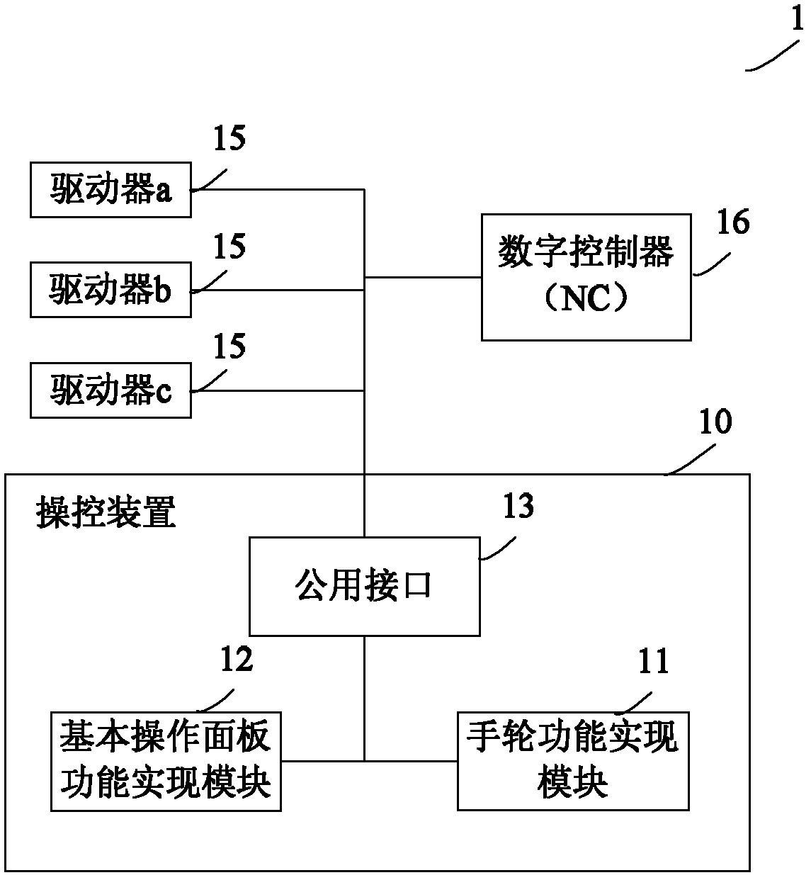
[0052] 1. The basic operation panel (BOP) is a human-computer interaction panel, which does not store any data of the drive itself, and the BOP does not need to recognize different drives. For example, assuming that the three drivers in the machine tool system all contain the parameter P20, if you want to modify the value of P20 of the first driver, after connecting the BOP to the first driver, the BOP does not need to recognize that the connected one is the first driver. Several drives, it only needs to directly read and modify the value of P20. Therefore, it is not necessary to have a BOP for each drive in the machine tool system, that is, one BOP can be used to serve multiple drives;

[0053] 2. When using a single BOP to serve multiple drives, for example, when debugging the drives, you can connect the single BOP to each drive one after another to set parameters and debug for these ...


PUM


Abstract

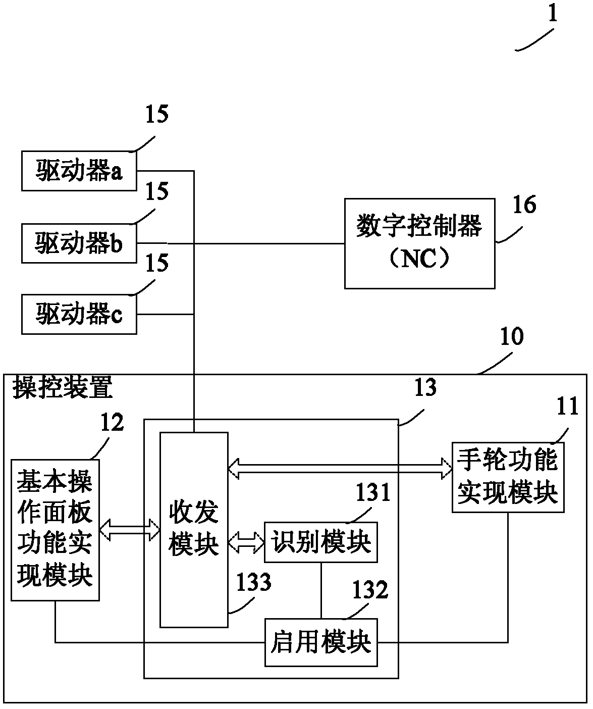
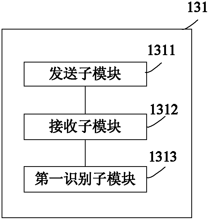
The invention discloses a control device for a machine tool system and the machine tool system. The machine tool system comprises at least one driver and a digital controller. The control device comprises a shared interface, a handwheel function implementing module and a basic operation panel function implementing module, wherein the shared interface is suitable to be connected to any one of the drivers and the digital controller; the handwheel function implementing module is used for implementing a handwheel function for the digital controller; the basic operation panel function implementing module is used for implementing a basic operation panel function for the drivers; the shared interface comprises an identification module, a starting module and a transceiving module; the identification module is used for identifying whether the type of equipment connected to the shared interface is the digital controller or the driver; the starting module is used for starting the handwheel function implementing module when the identification module identifies that the type of the equipment connected to the shared interface is the digital controller and starting the basic operation panel function implementing module when the identification module identifies that the type of equipment connected to the shared interface is the driver; and the transceiving module is used for transmitting data between the started module and the equipment connected to the shared interface. After the scheme disclosed by the invention is adopted, the cost of constructing the machine tool system can be reduced.

Description

technical field [0001] The invention relates to the field of machine tools, in particular to a control device for a machine tool system and a machine tool system with the control device. Background technique [0002] A machine tool system, especially a CNC machine tool system usually includes a machine tool body, a numerical controller (NC, Numeric Controller) and at least one driver. In particular, in a standard CNC machine tool system configuration, usually two or three drives are configured for one numerical controller. The main body of the machine tool includes, for example, components such as a frame, an input device (such as a handwheel), at least one motor, and the like. The driver is used to control the motor to drive the load to move. The digital controller controls the corresponding drives according to the predetermined program. As an input device for machine tools, handwheels are generally used for manual operation when required. Typically the handwheel can be...

Claims


Application Information

Patent Timeline
Patent Type & Authority Applications(China)
IPC IPC(8): G05B19/18
Inventor 倪松
Owner SIEMENS AG
Learn More