Lamellar separator with sump

A flake-like separator technology, applied in separation methods, dispersed particle separation, chemical instruments and methods, etc., can solve the problems of being taken away or discharged

Active Publication Date: 2016-06-29
BALKIS - TOURE
View PDF6 Cites 0 Cited by
  • Summary
  • Abstract
  • Description
  • Claims
  • Application Information

AI Technical Summary

Problems solved by technology

The problem with these lamellar separators known from the prior art is that, despite the drain, the liquid located in the sump is swirled or entrained by the fluid flow flowing through the laminar separator, or due to Forms a vortex to spiral upward into and be carried away or expelled from the lamellar separation space

Method used


Image

  • Lamellar separator with sump
  • Lamellar separator with sump
  • Lamellar separator with sump

Examples


Embodiment Construction

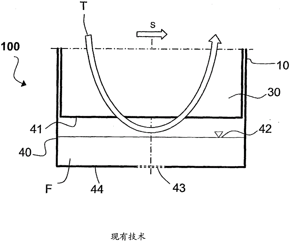
[0019] figure 1 The lower base region of a lamellar separator 100 according to the prior art is shown. The lamellar separator 100 is surrounded by a housing 10 into which the sump 40 is integrated. The laminar separator 100 has vertically oriented laminar profiles placed parallel to each other and spaced apart, the laminar profiles together forming a lamellar separation space, figure 1 Only the lower part of an individual laminar profiled part 30 can be seen in FIG. The lower edge of the lamellar profile 30 is indicated by 31 . The liquid-laden fluid flows through the lamellar separator 100 in a specific flow-through direction S, and the liquid droplets are separated from the flowing fluid on the wall surfaces of the laminar separator 30 in a known manner. The separated droplets coalesce and drain downwards due to gravity into a sump 40 provided for this purpose. The collected liquid F can be discharged through a discharge opening 43 (shown by dotted lines) located in the ...


PUM


Abstract

The lamella separator (100) comprises two spaced and vertically aligned lamella profiles (30), which form a flow channel between the profiles for conveying the liquid-loaded fluid. The liquid drops are separated on the wall surfaces two spaced and vertically aligned lamella profiles. A collection tray (40) is arranged below the lamella profiles for incorporating the liquid separated from the liquid-loaded fluid. The collection tray has a partition wall, which divides the collection tray into multiple areas.

Description

technical field [0001] The invention relates to a laminar separator for separating liquid droplets from liquid-charged fluids, having at least two substantially vertically oriented lamellar profiles, the at least two substantially vertically oriented laminar The sheet-shaped forming parts are separated from each other and guide the fluid with liquid between them, the liquid droplets are separated on the wall surfaces of the at least two substantially vertically oriented sheet-like forming parts, and have A sump for receiving liquid separated from the liquid-laden fluid is provided under the laminar profile. Background technique [0002] Laminar separators of this type, also known as lamellar droplet separators, are known in the prior art and are used in various processes for separating liquid droplets from liquid-laden fluids, in particular gas streams. In power stations such as solar or atomic power stations, the efficient separation of droplets from wet steam determines t...

Claims


Application Information

Patent Timeline
Patent Type & Authority Patents(China)
IPC IPC(8): B01D45/08B01D45/18
CPCB01D45/08B01D45/18
Inventor 吉多·邦塔伊耶尔德·施图肯施奈德约尔格·斯塔尔赫特
Owner BALKIS - TOURE
Why Eureka
Try Eureka